


Tractive Effort and Acceleration of Vehicles.
Page 14
Page 15
If you've noticed an error in this article please click here to report it so we can fix it.
The subject of the present paper does not in itself possess any vast degree of novelty, and it is not one that offers great scope for original thought. In this contribution, it has been the author's endeavour to deal with some of the more generally neglected aspects of the subject, and to demonstrate the method employed by him for the measurement and recording of acceleration and tractive effort, also to show the uses and value to the automobile engineer of acceleration diagrams.
Measurement of Acceleration.
In years gone by the only known method of measurement of acceleration was by observations of the time required to attain a given velocity, the mean acceleration during the period comprised by the observation being thus obtained. The same method in another form involves observations of the displacement of the vehicle from its point of rest, the time being recorded for a number of measured points along the track ; from data so obtained a plotting is made, and the curve so given is transformed by successive differentiation first into a velocity curve, and then into an acceleration curve.
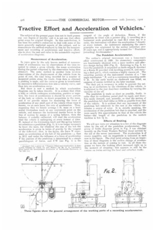
But there is now a method by which acceleration diagrams can be taken directly. It is evident that when a body or vehicle undergoes acceleration, positive or negative, the force of acceleration is shared by every portion of the body or vehicle, in direct proportion to the mass, and if we provide means for measuring the force of acceleration of any small part of the vehicle whose mass is known, we at once know the rate of acceleration. Thus, supposing that we loosely arrange 1 lb. mass on a horizontal frictionless track at any convenient point on the vehicle, and measure the horizontal inertia forces in the Tine of motion by means of a spring balance, then the balance, if suitably calibrated, will read the acceleration that the vehicle is undergoing at every instant of time. If, instead of the frictionless track and the spring balance we substitute a pendulum (Fig. 1), it is no longer necessary to know the mass, for whatever the size of the bob the acceleration is given in terms of gravity by the tangent of the deflection ; thus. in the figure, the force W represents an acceleration of the bob of the pendulum = y, that is, 32.2, and under the influence of a force of acceleration F the position of the pendulum is determined by a simple parallelogram of forces, and F,'W (see Fig. 1) is the
tangent of the angle of deflection. Hence, if the pendulum be fitted with a pointer (Fig. 1) recording on a horizontal scale graduated to read 32.2 when tan 0 is unity, the instrument will show the acceleration f directly at every instant. Au instrument embodying the above principles was originated by the author somewhat over 20 years ago, and is appropriately termed the " Pendulum (recording) Accelerometer."
The Pendulum Accelerometer.
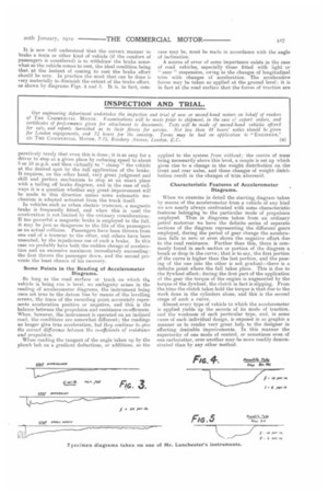
The author's original instrument was a home-made affair constructed in 1889. Its elementary components are functionally identical with a more modern and effective design dating 1904 (Fig. 2). Referring to Fig. 2, we have the pendulum A suspended on knife edges B, mounted on a frame M provided with levelling screws N, and carrying a dash pot L, which contains a highly viscous oil. The recording portion of the instrument consists of a " tan angle mechanism " E, and in a continuous recording outfit G H. In the early model no clockwork was fitted, an omission of course rectified in the later machine.
The dash pot is necessary in order to prevent the setting up of oscillations by the vibrations of the vehicle ; it is adjusted to the just dead-beat condition by varying the viscosity of the oil.
The pendulum is made as short as possible, firstly. in order that its oscillation period shall he rapid, and therefore easily damped, and, secondly, so that the motion of the pendulum bob shall differ as little as possible from that of the vehicle. it is evident that any movement of the pendulum bob relatively to the rest of the vehicle constitutes a source of error. It is, strictly speaking, the acceleration of the pendulum bob that is recorded, and the more nearly this approximates to that of the vehicle the better—the length of the pendulum in the modern machine is but It in.
Effects of Braking.
We will now turn our attention to a few of the diagrams taken by the aid of the pendulum accelerometer. The group of brake diagrams given in Fig. 3 was obtained recently on the Great Western Railway (local service) by the aid of the newer instrument. The acceleration is of cours3 negative, and its magnitude is indicated in each case in the figure. The chief point arising from an inspection of these diagrams is the sudden change of acceleration at the instant of coming to rest. In all these diagrams we have the braking effort increased right up to the moment of stopping; this appears to still he the custom on trains serving the held and suburban traffic.
It is now well understood that the correct manner to brake a train or other kind of vehicle (if the comfort of passengers is considered) is to withdraw the brake somewhat as the vehicle comes to rest, the ideal condition being that at the instant of coming to rest the brake effort. should be zero. In practice the most that can be done is very materially to diminish the extent of the brake effort. as shown by diagrams Figs. 4 and 5. It is. in fact, corn paratively rarely that even this is done ; it is so easy for a driver to stop at a given place by reducing speed to about 5 or 10 m.p.h. and then virtually to " clamp " the vehicle at the desired spot by tho full application of the brake. It requires, on the other hand, very great judgment and skill and perfect mechanism to stop at an exact place with a tailing off brake diagram, and in the case of railways it is a question whether any great improvement will be made in this direction unless some automatic mechanism is adopted actuated from the track itself. In vehicles such as urban electric tramcars, a magnetic brake is frequently fitted, and when this is used the acceleration is not limited by the ordinary considerations. If too powerful a. magnetic brake is employed to the full, it may be just as dangerous to the life of the passengers as an actual collision. Passengers have been thrown from one end of a tramcar to the other, and others have been unseated, by the injudicious use of such a brake. In this ease we probably have both the sudden change of acceleration and an excessive maximum immediately succeeding : the first throws the passenger down, and the second prevents the least chance of his recovery.
Some Points in the Reading of Accelerometer Diagrams.
So long as the road surface or track on which tha vehicle is being run is level, no ambiguity arises in the reading of accelerometer diagrams, the instrument being once set true to the datum line by means of the levelling screws, the trace of the recording point accurately represents acceleration positive or negative, and this is the balance between the propulsion and resistance co-efficients. When, however, the instrument is operated on an inclined road, the conditions are somewhat different; the readings no longer give true acceleration, but they continue to give the correct difference between'the co-efficients of resistance and propulsion.
'Allen reading the tangent of the angle taken up by the plumb bob on a gradient deductions, or additions, as the
case may be, must be made in accordance with the angle of inclination.
A source of error of some importance exists in the case of road vehicles, especially those fitted with light or " easy" suspension, owing to the changes of longitudinal trim with changes of acceleration. The accelerative forces may be taken as applied at the ground level; it is in fact at the road surface that the forces of traction are applied to the system from without; the centre of mass being necessarily above this level, a couple is set up which gives rise to a change in the weight distribution on the front and rear axles, and these changes of weight distribution result in the changes of trim aforesaid.
Characteristic Features of Accelerometer Diagrams.
When we examine in detail the starting diagram taken by means of the accelerometer from a vehicle of any kind we are nearly always confronted with some characteristic features belonging to the particular mode of propulsion employed. Thus in diagrams taken from an ordinary petrol motorcar we have the definite series of separate sections of the diagram representing the different gears employed, during the period of gear change the acceleration falls to zero or even shows the negative effort due to the road resistance. Further than this, there is commonly found in each section or portion of the diagram a break or drop in the curve; that is to say, the first portion of the curve is higher than the last portion, and the passing of the one into the other is not gradual—there is a definite point where the fall takes place. This is due to the flywheel effect ; during the first part of the application of the gear the torque of the engine is augmented by the torque of the flywheel, the clutch in fact is slipping. From the time the clutch takes hold the torque is that due to the work done in the cylinders alone, and this is the second stage of such a curve. Almost every type of vehicle to which the accelerometer is applied yields up the secrete of its mode of traction, and the weakness of each particular type, and, in some eases of each individual design, is exposed in so graphic a manner as to render very great help to the designer in effecting desirable improvements. In this manner the superiority of one mode of control, or sometimes even of one carburetter, over another may be more readily demonstrated than by any other method.