


A ROTARY SLEEVE VALVE AND GEAR.
Page 30
If you've noticed an error in this article please click here to report it so we can fix it.
A Résumé of Recently Published Patents.
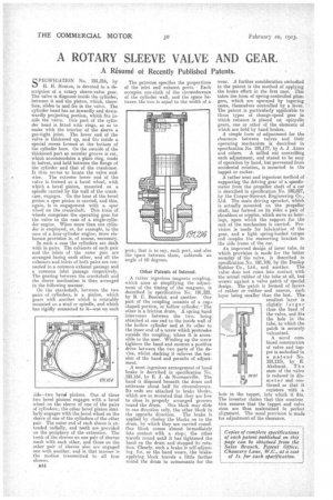
SPECIFICATION No. 191,216, by H. IL Heaton, is devoted to a description of a rotary sleeve-valve gear. The valve is disposed inside the cylinder, between it and the piston, which, therefore, slides to and ire in the valve. The cylinder head has an inwardly and downwardly projecting portion, which fits inside the valve. _tins part of the cylinder bead is fitted with rings, so as to make with the interior of the sleeve a gas-tight joint. The lower end of the valve is thickened up, and fits inside a special recess formed at the bottom of the cylinder bore. On the outside of the thickened part an annular groove is cut, which accommodates a plain ring, made in halves, and held between the flange of the cylinder and that of the crankcase. It thus serves to locate the valve endwise. The extreme lower end of the valve is formed as a bevel wheel, with which a bevel pinion, mounted on a spindle carried by the wall of the crankcase, engages. On the boss of the bevel pinion a spur pinion is carried, and this, again, is in engagement with a spur wheel on the crankshaft. This train of wheels comprises the operating gear for the valve in the case of a single-cylinder engine. When more than one cylinder is employed, as, for example, in the case of a four-cylinder engine, more elaborate provision is, of course, necessary.
In such a case the cylinders are dealt with in pairs. The exhausts of each pair and the inlets of the same pair are arranged facing each other, and all the exhausts and inlets of both pairs are connected to a common exhaust passage and a common inlet passage respectively. The gearing between the crankshaft and the sleeve mechanism is then arranged in the following manner.
On the crankshaft, between the two -pairs of cylinders, is a pinion, which gears with another which is rotatably mounted on a stud or spindle, and which has rigidly connected to it—one on each i'de—two bevel pinions. One of these two bevel pinions engages with a bevel wheel on the sleeve of one of the pairs of cylinders; the other bevel pinion similarly engages with the bevel wheel on the sleeve of one of the cylinders of the other pair. The outer end of each sleeve is extended radially, and teeth are provided on the periphery of the extension. The teeth of the sleeves on one pair of sleeves mesh with each other, and those on the other pair of sleeves also are engaged one with another, and in that manner is the motion transmitted to all four sleeves.
P44 The patentee specifies the proportions of the inlet and exhaust ports. Each occupies one-sixth of the circumference of the cylinder wall, and the space between the two is equal to the width of a port; that is to say, each port, and also the space between them, subtends an angle of 60 degrees.
Other Patents of Interest.
A rather ingenious magneto coupling, which aims at simplifying the adjustment of the timing of the magneto, is described in specification No. 191,222, by B. C. Bostwick and another. One part of the coupling consists of a cups shaped portion, or hollow cylinder.The other is a friction drum A spring band intervenes between the two, being attached at one end to the inside wall of the hollow cylinder and at its other to the inner end of a screw which protrudes outside the coupling, where it is accessible to the user. Winding up the screw tightens the band and ensures a positive drive between the two parts of the device, whilst slacking it relieves the tension of the band and permits of adjustment.
A most ingenious arrangement of band brake is described in specification No. 191,164, by E. J. de Norrnanville. The band is disposed beneath the drum and embraces about half its circumference. Its ends are attached to brake blocks, which are so mounted that they are free to close in properly arranged grooves round the drum. One block may slide in one direction only, the other block in.
the opposite direction. The brake is applied by closing the blocks on to the drum, by which they are carried round. One block comes almost immediately into contact with a stop; the other travels round until it has tightened the band on the drum and stopped its rotation. Clearly, such a brake is self-adjusting. for, as the band wears, the brakeapplying block travels a little farther round the drum to compensate for the wear. A further consideration embodied in the patent is the method of applying the brake effort, in the first case. This takes the form of spring-controlled plungers, which are operated by tapering came, themselves controlled by a lever. The patent is particularly applicable to those types of change-speed gear in which reliance is placed on epicyclic gears, one or other of the elements of which are held by baud brakes.
A simple form of adjustment for the clearance between valves and their operating mechanism is described in specification No. 191,177, by A. J. Amos and others. A milled nut controlling such adjustment, and stated to be easy of operation by hand, but prevented from accidental rotation, is mounted in the tappet or rocker.
A rather neat and ingenious method of supporting the driving gear of a speedometer from the propeller shaft of a car is described in specification No. 190,827, by the Cooper-Stewart Engineering Co., Ltd. The main driving sprocket, which is actually mounted on the propeller shaft, has formed on its sides a pair of shoulders or nipples, which serve as bearings, upon which the support for the rest of the mechanism is carried. Provision is made for lubrication of the gear, and a light spring-loaded torque rod couples the srinnorting bracket to the side frame of the car. An improved design of inner tube, in which provision is made for the better security of the valve, is described in specification No. 191,109, by the Dunlop 'Rubber Co., Ltd., and another. The valve does not come into contact with the actual rubber of the tube at, all, but screws against a valve patch of special design. The patch is formed of layers of rubber or rubber and canvas, each layer being smaller than the last. The smallest layer is slightly larger than the head of the valve, and fits the hole in the tube, to which the patch is securely vulcanized.
A novel combined construction of valve and tappet is embodied in a patent No. 191,115), by E. Akehurst. T h e stem of the valve is reduced in diameter and continued so that it registers with a hole in the tappet, into which it fits. The inventor claims that this construe Lion ensures that the tappet and valve stem are thus maintained in perfect alignment. The usual provision is made for adjustment of the clearance.