


Patents Completed.
Page 32
If you've noticed an error in this article please click here to report it so we can fix it.
Complete specifications of the following patents will be sent to any address in the United Kingdom by the Sale Branch, Patent Office, Holborn, W.C., upon receipt of eightpence per copy.
A Very Novel Engine.
A. W. Wail, No. 297, dated 4th January, 1912. Cognate Application No. 12,406, dated 25th May, 1912.—The accompanying illustration shows a section of a four-cylinder engine in which the four cylinders are grouped round the central axis about which the cylinders arid crankcase. revolve. By thus utilizing the whole mass of the engine as a revolving part, the need for providing a flywheel is avoided, and the weight of the engine is considerably reduced. A separate crankshaft is provided for each piston. and this has on it a bevel-wheel meshing with a gearwheel on a fixed sleeve extending from the right-hand end of the engine down into the crankcase. The bevel wheels on the crankshaft have a planetary motion on this wheel when driven by the pistons, and therefore cause the whole crankcase to be carried round. The inlet and exhaust passages of the cylinders are led out to a cylindrical surface towards the right-hand end of the engine which bears against a sleeve to which the inlet and exhaust conduits (not shown) are con• nected. A second speed is obtained by providing a bevel-wheel on the left-hand side to engage with the bevel-wheels on each of the crankshafts, and to be driven by them. This wheel will be turned at twice the rate of the engine, and thereby gives a higher speed.
Light Connecting Rods.
H. H. Patrick, No. 12,118, dated 22nd May, 1912.—Connecting rods which corn bine great lightness with the necessary strength are formed out of sheet and tubular metal welded together. A pair of main parts are employed, each being pressed out of sheet steel, and forming one half of the rod, as illustrated in the • drawings. Two such parts are placed with their edges together and are welded autogenously or electrically. Openings are stamped in each of the ends to receive the bushes for the crank and gudgeon pin; lubrication of these bearings may be effected by a special pipe provided in the interior of the connecting rod.
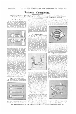
A Tip-over Jack.
W. E. Doyle, No. 13,370, dated 6th June, 1912.—The object of the present invention is to provide a tip-over jack which will not only act in either direction by the movement of the vehicle but which, when the vehicle is raised, will be locked in such position. The support is constructed in two parts which telescope within one another and are provided with interposed springs intended to take up ally shock. The upper member is mounted on the axle or any other suitable part of the chassis by an eccentric hearing which allows of the adjustment of the length of the supporting
member or, when required, of taking up wear. The locking of the support is provided for by a quadrant plate. This is provided with notches in which a lever is locked, and a suitable link connected to the supporting member holds the lever. The link has a spring coupling, as shown in the accompanying drawing, so as to avoid the transmission of shock to the mechanism. Three notches are provided in the quadrant, one of them in the middle, in which position the supporting member is kept upright, and one a short distance on either side; in either of these positions the supporting member is locked slightly to nne side with the toe of its foot engaging the ground, so prnyidina an additional braking action to stop the motion of the vehicle.
New Universal Joints.
S. I. Prescott, No. 11,335, dated 13th May, I912.—This specification describes a universal joint, in which the socket is provided with four cones mounted on shanks that are forced into holes in the socket. The cones are made of casehardened tool steel, while the socket is of somewhat softer, but similar, material. The cones extend inwardly in the socket, and engage tapered slots formed in a ball on the end of the other shaft. These slots are tapered to the same angle as are the cones—approximately 90 degrees—and this construction is such that
the torsional thrust of the cones causes a reaction which tends to force the shanks of the cones obliquely still further into their apertures in the socket. The risk of shearing the parts is thus considerably reduced. The arrangements for lubricating and excluding dust are also described and illustrated.
A Change-speed Gear, P. Marcellot, No. 26,645, of 1912, dated under International Convention, 21st November, 1911.—This change-speed gear consist* of a disc mounted on the driven shaft, and gearing with a pinion on the driving shaft. The pinion is tapered from one end to the other, and is provided with suitably-shaped inclined teeth meshing with similar teeth on the driven disc. The disc is mounted in a casing, which is trunnioned, so that the disc can be turned and brought into engagement with any part of the driving pinion. The disc runs freely in its own bearings, but drives the shaft through pins engaging slots in the ball-end of the shaft. The connection between the disc, and the shaft which it drives, may also be effected by providing the ball with teeth similar to those on the driving pinion, and by also making suitable teeth on the inner periphery of the disc. This arrangement of change-spced gear is reversible, and the tapered pinion may be on the driven shaft if desired.