


A n Improved
Page 46
If you've noticed an error in this article please click here to report it so we can fix it.
Brake Layout
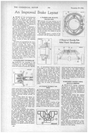
ABRAKE of the two-leading-shoe type is shown in patent No. 580,334 by F. Parnell and the Automotive Products Co., Ltd., Tachbrook Road, Leamington Spa. The aim of the design is simplicity, and a reduction in the number of working parts.
Upon the backplate is mounted a pair • of projections (I), which constitute abutment members for the adjacent ends of the two shoes, according to the direction of rotation. On the opposite side, the abutment faces comprise nuts (2) surrounding a right-and-left-handed screw. The latter is fitted with a worm wheel (3), the worm of which extends to the outside to form the adjusting means.
The shoes are expanded by the movement of a thrust block (4) in a radial direction towards the centre. The motion is transmitted vla push rods (5) to an elbow (6), rockably attached to the middle of the shoes. This layout is duplicated symmetrically on the opposite side, so that a toggle action is set Lip, which forces the shoes into contact with the drum. The shoes can, at the same time. move slightly in ft circumferential direction, so as to impart the leading-shoe effect.
ACCELERATION CONTROLLER
A DASH-POT for attaching to the rirack-rod of an injection pump for controlling the rate of acceleration, forms the subject of patent No. 580,285,
which comes from V. Fox, 1, Broadway Drive, Horsforth, Yorks. The device is rather more than a simple dash-pot; it functions also as an injector for uppercylinder lubricant during periods of acceleration.
The drawing shows the device attached to an injection pump. The rackrod (I) is joined to a piston (2) which can slide in a small cylinder. Connected to the working space are an inlet valve (3) and a discharge valve (4). Both inlet and discharge passages are fitted with adjustable leak-screws (5), which control the speed of action.
In operation, whenever the accelerator pedal is depressed, the action is limited in speed by the dash-pot, and a small quantity of fluid is expelled from the discharge port. The fluid is piped to the engine intake and is drawn into the cylinders with the air flow. Possible fluids are upper-cylinder lubricant, ordinary engine oil, water (as an antidetonant) or alcohol. The scheme is claimed to be equally suitable for petrol engines.