


Patents Completed.
Page 26
If you've noticed an error in this article please click here to report it so we can fix it.
LOCK NUT.—Davis.--No. 7,529, dated 28th March, 1906.—Each nut (B) is drilled through transversely along a line, which breaks into the bore of the nut, and -when the nut (B) is screwed home upon the bolt a pin (D) is driven into this hole, The pin is provided with a cutting end, to that
as it is driven in it cuts away that portion of the thread opposing its entrance, and the nut is thereby kept in place. The forward end of the pin can be burred over to retain it in place.
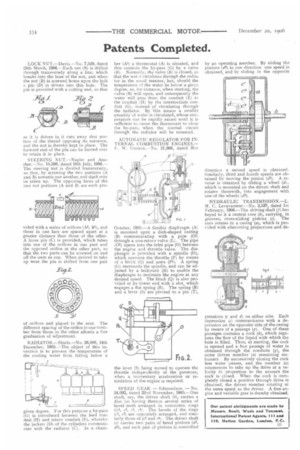
STEERING NUT.—Napier and Another.—No. 15,598, dated 10th July, 1906.— The steering nut is divided transversely, so that, by screwing the two portions (A and B) towards one another, end slack may he taken up. The opposing faces of the two nut portions (A and B) are each pro
vided with a series of orifices )A1, 131), and those in one face are spaced apart at a greater distance than those of the other. A loose pin (C) is provided, which takes into one of the orifices in one part and the opposed orifice in the other part, so that the two parts can be screwed on and off the stem as one. When desired to take up wear the pin is shifted from one pair
of orifices and placed in the next. The different spacing of the orifice in one member from those in the other affords a fine graduation of adjustment.
RADIATOR.—Shiels.—No. 26,080, 14th December, 1905,—The object of this in. vention is to prevent the temperature of the cooling water from falling below a given degree. For this purpose a by-pass (G) is introduced between the feed conduit (H) and return conduit (E), whereby the jackets (D) of the cylinders communicate with the radiator (C). In a chain.
ber (Al) a thermostat (A) is situated, and this controls the by-pass (G) by a valve (B). Normally, the valve (B) is closed, so that the watr circulates through the radiator in the usual manner, but, should the temperature of the water be below a givzn degree, as, for instance, when starting, the valve (13) will open, and consequently the water will pass from the conduit (E) to the conduit (H) by the intermediate conduit (G), instead of circulating through the radiator. By this means a smaller quantity of water is circulated, whose temperature can be rapidly raised until it is sufficient to cause the thermostat to close the by-pass, when the normal circuit through the radiator will be resumed.
AUTOMATIC REGULATOR FOR INTERNAT. COMBUSTION ENGINES.— F'. W. Gunton.—No. 21,368, dated 31st
October, 1905.—A flexible diaphragm (A) is mounted upon a dish-shaped casting (B) communicating with a pipe (01) through a non-return valve (L). The pipe (01) opens into the inlet pipe (0) between the engine and throttle valve. The diaphragm is provided with a spindle (D), which operates the throttle (P) by means of a block (Q) and arms (P1). A spring (G) surrounds the spindle, and can be adjusted by a bellcrank (H) to enable the diaphragm to maintain the engine at any desired speed. The block (Q) is also provided at its lower end with a slot, which engages a flat spring (R). The spring (R) and a lever (S) are pivoted to a pin (T),
the lever (S) being moved to operate the throttle independently of the governor, when a momentary acceleration or retardation of the engine is required.
SPEED GEAR. — Edmondson. — No. 24,092, dated 22nd November, 1905.— One
shaft, say, the driven shaft carries a disc (a) having thereon several series of bevel teeth arranged in concentric rings ({ei, ce, e3, el). The bevels of the rings (et, c2) are oppositely arranged, and similarly those of (c3 and c4). The driven shaft (e) carries two pairs of bevel pinions (ell, d2), and each pair of pinions is controlled by an operating member. By sliding the pinions (d2) in one direction one speed is obtained, and by sliding in the opposite direction a second speed is obtained. Similarly, third and fourth speeds are obtained by moving the pinion (d1). A reverse is obtained by sliding a wheel (d), which is mounted on the driven shaft and rotates therewith, into engagement with one of the wheels (d2).
HYDRAULIC TRANSMISS1ON.—L. M. C. Levavasseur.—No. 2,537, dated 1st February, 1906.—The driving shaft (f) has keyed to it a central core (b), carrying, in grooves, cross-sliding pistons (e). The core rotates in a casing (a), which is provided with alternating projections and de pressions (e and d) on either side. Each depression (c) communicates with a depression on the opposite side of the casing by means of a passage (g). One of these passages contains a cock (Is), which regulates the flow of the liquid with which the hole is filled. Thus, at starting, the cock is opened and a free passage of water is obtained through the conduits (g), the outer driven member (a) remaining stationary. By successively closing the cock less water passes, and the member (a) commences to take up the drive at a velocity in proportion to the amount the cock is closed. When the cock is completely closed a positive through drive is obtained, the driven member rotating at the same speed as the driver. A free engine and variable gear is thereby obtained.