


From Engine to Axle.
Page 15
Page 16
If you've noticed an error in this article please click here to report it so we can fix it.
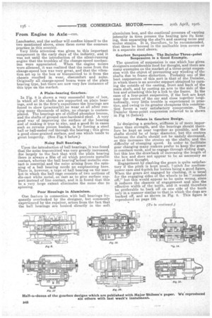
Following the recent papers read before the Institution of Automobile Engineers, which have dealt respectively with rear axles and engines, a third has now been read, dealing with those parts of the transmission which were not included in the previous two reviews. Major Shilson, the author, disclaims any intention to "present any new features or enunciate any new theories," but he has dealt with his subject in an informative manner, and we therefore reproduce the paper in instalments as opportunity occurs. The present instalment follows that on page 127 last.
Most Satisfactory Type.
In the author's opinion, the most satisfactory type of clutch is the single plate, as illustrated in Figs. 5, 6, 7, and for which the formulm are given in the APpendix. A single plate is held between one face of the flywheel and a ring capable of sliding axially on pins or keys, which forms part af the flywheel. The leverage which is lost by not using the cone is regained through the mediumof the operating levers, which can be so proportioned as to give any tatio required within reasonable limit. Figs. 5, 6 and 7, referred to above, were reproduced at the bottom of page 127 of our last issue, No. 579.
Single-plate Clutches. • In Fig. 4 is shown a single-plate clutch, in which the pressure ring adjustment is niade by a large screwed ring having an annular groove which forms the fulcrum for the operating levers, and a central clutch spring, whereas in Fig. 5 this snring has been replaced by six smaller ones in the periphery of the flywheel, which makes the arrangement very much more compact and reduces the overhang from the engine bearing,. and as all the parts are then easily turned, balance is much more 'easily obtained. It will be observed that the clutch shaft is driven in this case through the medium of six steel balls sunk into recesses of the ball-ended shaft and each sliding in grooves of the clutch plate. boss, thus presenting a flexible joint of very compact proportions and one which does not necessitate any balancing to make it run true, six -4: in. diameter balls at 11 in. pitch circle diameter being used for a four-cylinder engine 100 ram. by 130 mm. Two other illustrations of the single-plate clutch are given in Figs. 6 and 7. In Fig. 6 it will be noted that the clutch shaft spigots into a hearing in the crankshaft flange, whereas in Fig. 7 it is held in position by a spherical bearing, the driving attachment of which is separate from the driven-plate bearing.
Clutch Withdrawal Gear.
An apparently small detail, but one which is liable to 'give considerable trouble, is in the clutchwith drawal arrangements, for in spite of appearances to the contrary, it is not sufficient to use an ordinary thrust bearing for this purpose ; in facie a journal bearing is preferable to a thrust bearing, unless the latter is efficiently supported by a plain or ball journal. The operating levers should be arranged so that no axial thrust is imposed, and probably the best arrangement is for the levers to have small ball journals mounted on pins and held away from the clutch withdrawal collar when not -in operation.
An extra, large grease cup should be fittedto the withdrawal, collar to save very frequent attendance. One or two makers have used a white-metal-faced clutch-withdrawal ring, but owing to the large size and the difficulty of lubrication, and the consequent heat generated by slipping the clutch, or even by the rubbing' thrust imposed by the weight of the pedal, the-white metal is prone to tun out, and as soon as this happens it is practically impossible to dc-clutch owing-to the small amount of effective movenient then available.
Pedals, their Pads and TraveL Pedal Pressure Should Not Exceed 50 lb.
To prevent the foot slipping off the pedal, seine makers east a lip on the side of the pad, but this is -apt to be a disadvantage in the case of a driver with a; large foot. One of the most satisfactory methods is that adopted by the Maud-slay Co., in which the pedal pad is Cast with a small rib all round the edge and the face of the depression carefully cleaned up, tinned and filleein with lead, and this, produces a very neat non-slipping surface. The load necessary to withdraw the clutch is frequently much too great and imposes a strain on the driver's leg on a long day's run in traffic. The pedal pressure should not exceed a load of about 30 lb. but care should be taken that it is not tie light; or the unconscious pressure of the foat resting in position on the pedal will cause the, clutch to slip. Care should also be taken that the travel of the pedal pad is along a path which is comfortable to the driver, and if it is necessary for the pad to be high up from the footboards, a,heel rest will prove a great comfort, and the driver will be more likely to take an intelligent interest, in the running. of his vehicle..
The Effect of the Clutch on Other Units.
The clutch is responsible for a number of troubles which appeared. either in the engine or the gearbox and which were at first difficult to locate. It is very necessary that the 'driving shaft should be entirely free. except at its attachment to the universal joints, one of which should be right in the heart of the clutch iaself, and not at some considerable distance outside of it as -on many designs.
In some cases the withdrawal sleeve takes its bearing in the spring adjustment nut (see Fig. 4), and OD account of the thread never runs true, and so causes a distinct -loss of balance which at high speeds produces vibration.
Change-speed Bexes. •
Roughly speaking, the change-speed boxes in use at the present time are of either spur or silent chain types. There are a small number of epicyclic gearboxes on the market, chiefly of American design, but practically the only one now existing in this country is the 134.7 Lanchester, and the author will confine himself to the two mentioned above, since these cover the common practice in this country. Very little attention was given to this important component in the early days of the industry, and it was not until the introduction of the silent-running engine that the troubles of the change-speed mechanism were appreciated. When the engine noises were silenced, it was realized that the noise from the change-speed box was very great, and that the vibration set up in the box or transmitted to it from the chassis resulted in wear, discomfort and noise. Originally all change-speed boxes were of the plain bearing type, but there are now very few instances of this type on the market.
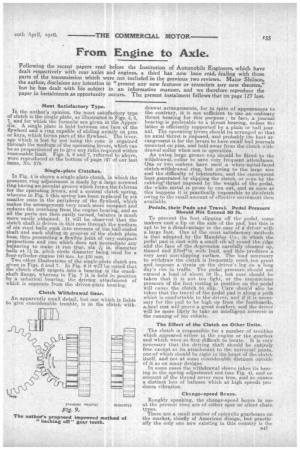
A Plain.-bearing Gearbox.
In Fig. 8 is shown a very successful type of box, in which all the shafts are supported on plain bearings, and as in the firm's experience the bearings are found to show (practically) no wear at all after running many thousands of miles, DO change is contemplated. The bearings are of chilled phosphor bronze, and the shafts of ground case-hamdened steel. A very good way of improving the surface of the bearing and of making it true to size, and a good fit in cases such as reverse pinion bushes, is by forcing a steel ball or ball-ended rod through the bearing ; this gives a good close-grained surface, and one which tends to great longevity. (See Fig. 8 below.)
Noisy Ball Bearings.
Upon the introduction of ball bearings, it was found that the noise transmitted was very greatly increased, clue largely to the fact that with the plain bearing there is always a film of oil which prevents metallic contact, whereas the ball bearing:actual metallic contact is essential and the noise arising from the spinning of a ball bearing needs no emphasizing here. There is however, a type of ball bearing on the market in which the ball cage, consists of two sections of die-cast white metal, so cast as to give surface support -instead of line contact, and it is found that this to a very large extent eliminates the noise due to spinning.
Poor Housings in Aluminium.
One feature in connection with ball bearings irequently overlooked by the designer, but commonly experienced by the repairer, arises from the fact that the ball bearings are housed directly in the soft
aluminium box, and the continual pressure of varying intensity in time presses the bearing into its housing, thus separating the shafts and causing noise and -undue strains. It is therefore, to be recommended, that these be housed in the malleable iron covers or in a separate steel sleeve.
Gearbox Suspension. The Daimler Three.-point Suspension is a Good Example.
The question of suspension is one which has given designers eon.siderable food for thought, and there are many examples on the market of a three-point suspension with the object of preventing any winding of the shafts due to frame distortion. Probably one of the best suspensions of this sort is that of the Daimler, in which there is an annular support obtained by turning the outside of the casting, front and back of the main shaft, and by casting an arm to the side of the box and attaching this by a link to the frame. In the case of a four-point suspension, if the feet are kept near the centre of the car and close together longitudinally, very little trouble is experienced in practice, and owing to its greater cheapness this construction forms a very satisfactory compromise. The , Daimler three-point suspension referred to is shown in Fig 14 (below).
Points in Gearbox Design.
In-designing a gearbox, stiffness is of more importance than strength, and the bearings should therefore be kept as near together as possible, and the shafts should be of large diameter, but the centres between the shafts should not be unduly decreased, as this increases the strains on the shafts, and the difficulty of changing speed. In order to facilitate gear changing many makers prefer to keep the gears in constant mesh, and to engage through sliding dogs, but this has the drawback of increasing the length of the box and does not appear to be as necessary as was at first thought. Engagement by clashing the gears is quite satisfactory if the pitch is kept small, 7-pitch for mediumpower cars and 6-pitch for lorries being a good figure. When the gears are engaged by clashing, it is usual for the engaging sides of the wheels to be "rounded off," but this would appear to be quite wrong, since it reduces the chances of engagement and also the effective width of the tooth, and it would therefore be preferable to back off on one side of the tooth only in a manner similar to that in which the dogs are backed off, and as shown in Fig. 9. This figure is reproduced on page 155; (To be continued.)