


Interesting Features in the Simms-Welbeck System.
Page 14
Page 15

If you've noticed an error in this article please click here to report it so we can fix it.
The Simms Manufacturing Company, Ltd., of Welbeck Works, Kimberley Road, Kilburn, N.W., are manufacturing three different groups of engines, with cylinders of settled dimensions as regards bore and stroke, both for their own requirements and for sale to builders of motor vehicles ia all parts of the world. The trade in the sale of engines has been established for many years and is now of very considerable proportions. The cylinder dimensions of the three classes are (a) 82 by 9om.m., giving 31, 6-7, and 12-15b.h.p., for one, two, and four cylinders respectively ; (b) 95 by nom.m., giving 5-6, 8-to, and 2o-24b.h.p.; and (c) Ito by
tom.m., giving 6-8, 12-14, and 26-3ob.h.p. In all the multi-cylinder engines the cylinders are cast in pairs with a gap between the water jackets, and all have both the inlet and exhaust valves on one side,. which design was first made by Mr. F. R. Simms. Only one cam shaft is used to operate both sets of valvts and the igniters. All the parts are made at the company's Chesterfield works and are subjected to a second inspection after arrival at Khnberley Road, but before they are taken into stores there, a wellconsidered system of bonus payments being in use throughout the several departments. We were particularly impressed by the care exercised in testing the engines for their b.h.p., and it may be noted that the testing shop has no less than 20 beds for that purpose, where every engine, from the single-cylinder 31h.p. to the latest marine type giving toob.h.p., is run for many hours before being passed to the erecting shop.
The output of the Simms Manufacturing Company has grown so enormously since the removal of the works from Southwark Park Road some two years ago, that an imniediate further extension of the present large works is about to be undertaken. We have selected a few of the many interesting features in the " Simms-Welbeck " system, and we shall give particulars of Mr. Simms' intended developments in our next issue.
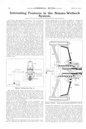
Fig. x is a sectional elevation of the carburetter, and dearly presents the leading points in its construction. The petrol jet has four small orifices, and the inverted conical valve is carried on a sleeve which travels up and clown on the jet stem. At low engine speeds the principal volume of air is taken through the small holes in the valve sleeve, immediately above the level of the jet, hut any increase in the revolutions results in a proportional extra admission of supplementary air passing by the conical face of the valve by reason of the increased area of the opening caused by the greater suction in the passage. Too big a lift is prevented by the stop fixed in the induction tube. The mixing chamber is jacketed, and a branch from the exhaust pipe is connected to it.
Fig. 2 shows the arrangement of the clutch and the provision for adjusting the grip between the faces (AA). The
female portion (B) of the clutch is bolted to a flange (C) formed on the back end of the crank shaft (D). A short extension (E) of the crank shaft, which has two spiral oil grooves for lubricating purposes, makes a bearing on which a long gun-metal bush (F) is a working fie The bush is threaded at its largest diameter, as shown, and is immovably fixed in a hollow cast-iron shell (G), to which is bolted the male half (H) of the clutch. The method adopted for adjusting the pressure between the clutch faces consists in the movement of the gun-metal cylinder (I) which is contained within the shell (G). This cylinder (I) has two internal diameters; the smaller one is threaded to fit the screw on the bush (F), whilst the larger diameter surrounds one end of the clutch spring (K). The pressure is received through the interposition of a ball race (I.), consisting 01 two steel rings between which balls race. The forward end of the clutch spring abuts against the inner central portion of the female half of the clutch. Eight " tommy " holes (M) are disposed around the nut end of the cylinder (I), and these are reached through two oblong openings placed diametrically, but not shown in the drawing, in the hollow shell (G). To save undue slamming of the clutch and to allow of its coming into action gently, a " dashpot " is used. This is seen in Fig. 3. A cylinder (A) contains a piston (13) and piston rod (C), which can he lengthened or shortened by unscrewing the lock nut (I)) should this at any time be necessary for adjustment. The piston is made up of a grooved
plate (E)—which screws on a threaded portion of the piston rod—against which is placed a cup leather (F), and lastly an aluminium disc (G) is screwed on. The separate members of the piston head are held in place by a small screw (II). When the clutch pedal is depressed the piston is withdrawn by the lever, and on the pedal being released the piston is forced forward, cushioning the induced air between itself and the end of the cylinder. On the cylinder head is :.tn adjustable conical valve for the slow release of the compressed air. The oiler (L) is for lubrication if required.
The main frame (A) of the universal joint, shown in elevation in Fig. 4, has two brackets (B) cast on its inner face. The outer side is hollow, with a boss (C) cast on it to receive the shaft from the gear box. A hood (D) serves to prevent the ingress of dirt to the hearing on the gear box. The connecting piece (E) of the universal joint has a socket (F) to receive the squared longitudinal driving shaft (G), whilst its forward extremity consists of two jaws (I) with circular ends, having eyes of large diameter bored through them. Placed in the bearing formed by these eyes is the bearing pin (K) flattened on its two opposite sides, and of such a length as to come flush with the two outer faces of the jaws (I). The bearing pin (K) has a hole bored through its centre to receive the bolt (L), and there are also two holes drilled in the brackets (B) for the same purpose. A tie bolt (M) is passed through the pin (K) and the bolt (L) to hold them firmly together. The universal joint is completely enclosed by a hollow casting (N), having a circular hole at 0 large enough to admit of a vertical or horizontal movement on the part of the socket piece (F). Dirt is kept out from the interior of the cover by a large leather washer (P) cut out to make a tight fit round the socket (F). The washer is adjusted to a friction tight fit by means of a screw cap (0) having an orifice (R) corresponding in size to the one in the casting at 0. The interior is greased through the removable plug (S). The whole arrangement is flexible and compact.
The proposal of the Croydon Corporation to run motor buses has been thrown out by the Parliamentary Committee to which the Bill was submitted. The principal opposition came from the British Electric Traction Company, the South Metropolitan Tramways Company, and the local authorities around. The case for Croydon was badly prepared.
Work will begin immediately on the site for the new works of Argyll Motors, Ltd., near Alexandria, in the Vale of Leven. The ground lies between the river Leven and the railway from Glasgow to Balloch. The new works will be situated three-quarters of a mile from Loch Lomond. The total area of the land purchased is 55 acres, of which 25 will be utilised for the works and offices. The remaining 30 acres will be devoted to dwelling houses for the employees and a recreation field.