


A New A.E.C. Combustion System
Page 46
If you've noticed an error in this article please click here to report it so we can fix it.
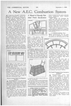
A &swine of Recently Published Patent Specifications AN improved oil-engine combustion system is disclosed in patent No. 509,838 by the Associated Equipment Co., Ltd., and W. Semmons, both of Southall, Middlesex. The main object is an improved intermixture of the air and fuel. The system requires an initial swirl to be imparted to the incoming air, and this is achieved by the use of a one-sided mask (1) on the inlet valve or a tangential slope of the air passage. The combustion space itself is located entirely in the piston crown, and is positioned slightly eccentric to the cylinder axis by an amount equal to about 3 per cent. of the bore. This slight offset, together with the slope of 4he injector, permits the use of a pair of valves of ample size.
An essential feature is the shape of the combustion chamber; the vertical section is clearly shown in the drawing, whilst a horizontal section would be circular at all points except for the recesses (2). These are four in number, and are placed so as to receive the four spray jets from the injector.
Heat Insulation For Brake Facings.
TO ensure that most of the generated heat is conducted to the brake drum, instead of to the more easily deformed
brake shoes, is the object of a new brake facing covered in patent No. 508,159, by General Motors Corp., Detroit, Mich., U.S.A. .
A heat-insulating layer (1) is employed between the facing proper and the shoes. The proposed insulating material is glass wool in fibrous form, fortified by a binding material made from colloidal lead or synthetic resin. Another advantage is that the facing does not absorb moisture so easily as does the conventional type.
Electro-vacuum Clutch and Magnetic Gearbox.
A TRANSMISSION and gear-change system, simple to operate and free from snatch, is described in patent No. 509,962 by Wolseley Motors, Ltd., and others, all of Drews Lane, Birmingham, 8. This scheme employs a poweroperated clutch in conjunction with a magnetic gearbox.
A gearbox of this type can, of course, function also as a clutch, but the patentees state that the normal type of clutch is more satisfactory, and stands up to wear better than the magnetic type; the latter is more inclined to snatch owing to its "all or nothing" A44
action. I To preserve sim
plicity of operation from the driver's standpoint, the normal clutch is to be operated by engine suction, reducing the number of pedal controls to two, and the patent is concerned with the electric control mechanism for the clutch, having respect to the gear selector.
Advantage appears tb have been taken of all possible means for controlling the automatic clutch operation. To begin with, it can be disengaged only when vacuum is available. Next, its vacuum cylinder is in connection with the induction pipe via two valves, one of which is closed when the accelerator pedal is depressed: Thus a condition for clutch' release is the foot off the accelerator.
The second valve is closed electrically when the gear lever is in second, third or fourth gears, so that the clutch can be disengaged only when it is in first speed or neutral. Further, an optional
device covered by the patent prevents clutch withdrawal, above dynamo charging slieed.
Thus, suction can disengage the clutch only when the gear lever is in neutral or first speed, and the throttle is practically closed and the engine is ticking over. Of these the first condition is to prevent the drive from being broken every time the accelerator is released, whilst the third seems to be mainly in the nature of a precaution.
The patent is significant in revealing the interest of one of the companies in the Nuffield group in the electro-magnetic gearbox.
A Deflation-resisting Tyre.
THE unpuncturable tyre has been the aim of hundreds of inventors, and efforts are still being made in this
direction. Patent No. 509,645 shows a tyre which, whilst not claimed to be unpuncturable, would, in the event of a puncture, at least enable the vehicle to continue at a reduced speed. The inventor is W. Lambert, 132, Herne Hill, London, S.E.24.
In this tyre, the inner tube is divided into a large number of separate compartments each fitted with its own inflation valve, although these may be interconnected if desired. To facilitate assembly, the chambers can be attached to a common band so that they may be handled in one piece. The drawing clearly shows the scheme, which is said to be specially suitable for military and heavy vehicles.
For Liquid Transport Under Emergency Conditions.
ACOLLAPSABLE water tank quickly adaptable to any vehicle for the purpose of decontamination or fire-fighting, is shown in patent No. 509,397 by J. Sparshatt, I, Old London Road, Hilsea, Portsmouth. The tank consists of two components, a waterproof fabric bag and a collapsable wire-mesh framing, the latter being shown in the drawing. When required for tie, the bag is placed inside the wire cage, and is held open by the pressure of the contained liquid. The upstanding members at the ends are for the purpose of carrying a fire-escape ladder.
The advantage of the scheme is the ease of storing large numbers of the units, owing to their compact form when folded.