


Substitute for Differential Gear
Page 46
If you've noticed an error in this article please click here to report it so we can fix it.
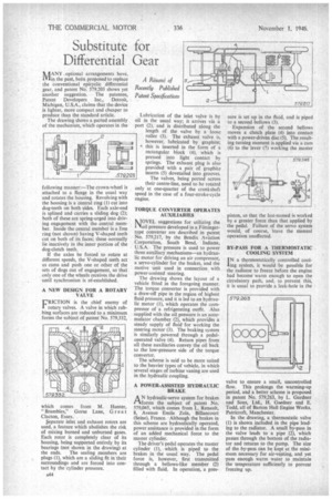
ItJjANY optional arrangements have, Min the past, been proposed to replace the conventional epicyclic differential gear, and patent No. 579,203 shows yet another suggestion. The patentee, Patent Developers Inc., Detroit, Michigan, U.S.A., claims that the device is lighter, more compact and cheaper to produce than the standard article. The drawing shows a parted assembly of the mechanism, which operates in the
following manner:—The crown-wheel is attached to a flange in the usual way and rotates the housing. Revolving with the housing is a central ring (I) cut into dog-teeth on both sides. Each axle-end is splined and carries a sliding dog (2); both of these are spring-urged into driving engagement with the central member. Inside the central member is a free ring (not shown) having V-shaped teeth cut on both of its faces; these normally lie inactively in the inner portion of the dog-clutch teeth.
If the axles be forced to rotate at different speeds, the V-shaped teeth act as cams and push one or other of the sets of dogs out of engagement, so that only one of the wheels receives the drive until synchronism is reestablished.
A NEW DESIGN FOR A ROTARY VALVE
FRICTION is the chief enemy of rotary valves. A valve in which rubbing surfaces are reduced to a minimum forms the subject of patent No. 579,332,
which comes from M. Hunter, "Brambles," Gorse Lane, Great Clacton, Essex.
separate inlet and exhaust rotors are used, a feature which abolishes the risk of mixing burned and unburned gases. Each rotor is completely clear of its housing, being supported entirely by its bearings (not shown in the drawing) at the ends. The sealing members are plugs (1), which are a sliding fit in their surroundings and are forced into contact by the cylinder pressure. Lubrication of the inlet valve is by oil in the usual way; it arrives via a port (2), and is distributed along the length of the valve by a loose roller (3). The exhaust valve is, however, lubricated by graphite; • this is inserted in the form of a rectangular block (4), which is pressed into light contact by springs. The exhaust plug is also provided with a pair of graphite inserts (5) dovetailed into grooves. The valves, being ported across their centre-line, need to be rotated only at one-quarter of the crankshaft speed in the case of a four-stroke-cycle engine.
TORQUE CONVERTER OPERATES AUXILIARIES MOVEL suggestions for utilizing the loll pressure developed in a Fottingertype converter are described in patent No. 579,217, by the Bendix Aviation Corporation, South Bend, Indiana, U.S.A. The pressure is used to power three auxiliary mechanisms—an hydraulic motor for driving an air compressor, a servo-cylinder for the brakes, and the motive unit used in connection with power-assisted steering.
The drawing shows the layout of a vehicle fitted in the foregoing manner. The torque converter is provided with a draw-off pipe in the region of highest fluid pressure, and it is led to an hydraulic motor (1), which operates the compressor of a refrigerating outfit. Also supplied with the oil pressure is an accumulator chamber (2), which provides a steady supply of fluid for working the steering motor (3). The braking system is similarly powered through a pedaloperated valve (4). Return pipes from all these auxiliaries convey the oil back to the low-pressure side of the torque converter.
The scheme is said to be more suited to the heavier types of vehicle, in which several stages of turbine vaning are used in the hydraulic coupling.
A POWER-ASSISTED HYDRAULIC BRAKE
AN hydraulic-servo system for brakes forms the subject of patent No. 579,045, which comes from L. Renault, 8, Avenue Emile Zola, Billancourt (Seine), France. Although the brakes in this scheme are hydraulically operated, power assistance is provided in the form of an added mechanical force to the master cylinder.
The driver's pedal operates the master cylinder (I), which is piped to the brakes in the usual way. The pedal force is, however, first transmitted through a bellows-like member (2) filled with fluid. In operation, a pres
sure is set up in the fluid, and is piped to a second bellows (3).
Expansion of the second bellows moves a clutch plate (4) into contact with a power-driven disc (5). The resulting turning moment is applied via a cam (6) to the lever (7) working the master valve to ensure a small, uncontrolled flow. This prolongs the warming-up period, and a better scheme is proposed in patent No. 579,263, by L. Gardner and Sons, Ltd., H. Gardner and E. Todd, all of Barton Hall Engine Works, Patricroft, Manchester.
In the drawing, a thermostatic valve (I) is shown included in the pipe leading to the radiator. A small by-pass in the valve leads to a pipe (2), which passes through the bottom of the radiator and returns to the pump. The size of the by-pass can be kept at the minimum necessary for air-venting, and yet pass enough warm water to maintain the temperature sufficiently to prevent freezing up.