


• A RICARDO DESIGN IN VALVE SEATINGS.
Page 62
If you've noticed an error in this article please click here to report it so we can fix it.
A Resume of Recently Published Patent Specifications.
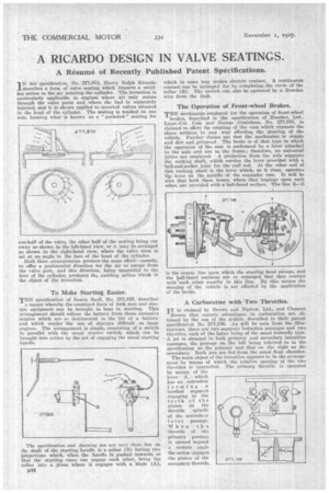
IN his' specification, No. 277,875, Harry Ralph Ricardo describes a form of valve seating which imparts a swirling action to the air entering the cylinder. The invention is particularly applicable to engines where -air only enters through the valve ports and where the fuel is separately injected, and it is shown applied to inverted valves situated in the head of the cylinder. The seating is masked on one side, forming what is known as a " pocketed " seating for
one-half of the valve, the other half of the seating being cut away as shown in the left-band view, or it may be arranged as shown in the right-hand view, where the valve stem is set at an angle. to the face of the head of the cylinder.
Both these arrangements produce the same effect—namely, to offer a preferential direction for the air to escape from the valve port, and this direction, being tangential to the bore of the cylinder, produces the swirling action which is the object of the invention.
To Make Starting Easier.
TBE specification of Saxon Snell, No. 277,828, describes a means whereby the combined force of both man and electric equipment can be brought to bear in starting. This arrangement should relieve the battery from those excessive strains which are so detrimental to the life of a battery and which render the use of starters difficult on large engines. The arrangement is simple, consisting of a switch in parallel with the usual starter switch, which can be roug,ht into action by the -act of engaging the usual starting tan dle.
The specification and drawing are not very clear, but on tiu; shaft of the starting handle is a collar (B) having two projections which, when the handle is pushed inwards so that the starting cams can engage each other, bring 'the Collar Into a plane where it engages with a blade (A), B44
which in some way makes electric contact. A continuous contact can he arranged for by completing the circle of the collar (B). The switch can also be -operated by a Bowden v.-ire from the dash.
The Operation of Front-wheel Brakes.
THE mechanism employed for the operation of front-wheel brakes, described in the specification of Humber, Ltd., Lieut.-Col. Cole and .George Grainham, No. 277,783, is claimed to effect the rotating of the cam which expands the shoes without in any way affecting the Steering of the vehicle. Further claims are that the mechanism is simple and dirt and gritproof. The brake is of that type in which the operation of the cam is performed by a lever attached to the 'axle and not to the frame ; therefore, no universal joints are employed. A projection from the axle supports the rocking shaft, which carries the lever provided with a ball-and-socket joint for the pull rod. At the other end of this rocking shaft is the lever which; as it -rises, operates the lever on the spindle of the expander cam. It will be seen that both these levers, where they impinge upon each other, are provided with a ball-faced surface. The line Z—Z
• s the centre line upon which the steering head swings, and the ball-faced surfaces are so arranged that they contact with each other exactly in this line. By this means the steering of the vehicle is not affected by the application of the brake.
A Carburetter withTwo Throttles.
T is claimed by Brown and Barlow, Ltd., and Clement 'Brown that certain advantages in carburation are obtained by the use of the system • described in their patent specification No. 277,736. As will be seen from the illustrations, there are two separate induction passages and two throttles, each of the latter being of the usual butterfly type. A jet is situated in both primary and secondary induction passages, the passage on the left being referred to in the specification as the primary and that on the right as the secondary. Both jets are fed from the usual float chamber.
The main object of the invention appears to be the arrangement by means of which the relative opening of the two throttles is controlled. The primary throttle is operated by means of the lever A, which has an extension forming a toothed segment engaging in the teeth of the pinion on the throttle spindle of the secondary inlet passage. When th a throttle of the primary passage is opened beyond a certain angle the sector engages the pinion of the secondary throttle