


LIGHTNESS IN THE NEW A.D.C. CHASSIS.
Page 54
Page 55
Page 56

If you've noticed an error in this article please click here to report it so we can fix it.
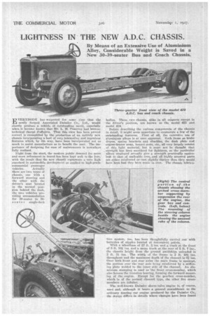
By Means of an Extensive Use of Aluminium Alloy, Considerable Weight is Saved in a New 30-39-seater Bus and Coach Chassis.
VERYBODY has aexpected for some time that the T.4 newly formed Assoeiated Daimler Co., Ltd., would shortly produce -a vehicle of outstanding merit, especially When it became known that -Mr. L. H. Pomeroy had become technical charge Waif-Ores. That this view has been proved correct is exemplified by the -production of an entirely new , chassis incorporating a host of very interesting and ingenious features which, -b.y the way, have been incorporated not so much to assist manufacture -as to benefit the user. The importance of -designing for ease of maintenance is 'nowadays. fully realized.
Right from the start, the -modern public demand for moreand more refinement in travel has been kept well to the fore,, with the result -that the -new chassis. represents a very high standard in automobile development as applied to high-grade commercial passenger
vehicles. Actually there are two types of chassis, one with a forward steering and the other with the driver's seat located in the normal position behind the dash, the two vehicles providing accommodation for 30-seater to 39seate r single-deck bodies. These twochassis, alike in all respects except in the driver's position, are known as the model 422 and model 424.
. Before describing the various components of the :chassis in detail, it might seem opportune to enumerate a few of the ontittandiag features. . Pirst of all, the extensive use of aluminium -alloys is at once apparent.. Such items as :brake drums; .spring brackets and shackles, the &rah Plate and engine-bearer -arms, bonnet rests, etc., all very largely consist of this light material, hut it must not be thought that strength has_been sacrificed for lightness, as the particular alloys employed .actually give a strength practically euttiva.
lent -thatof inalleable..iron,and all highly stressed parts . are either reinforced or east slightly thither than they would. have been -had they been mail.e in, iron. The chassis hibric-a lion system, too, has been thoughtfully carried Out with batteries Of nipples located at -Convenient points.
With a wheelbase of 17 ft. 2. ins. -a-nd a track at the front of .5 ft. 1.0i ins, and a mean track at the sear of 5 ft. 7 ins., the chassis bright from the ground amidships unloaded is 2 ft. 3i, ins. The width of the frame is 2 ft. 10Athroughout and the maximum depth of the channel is 8.2ins. Over both front and rear 'axles the main frame is Upswept, the portion over the rear axle being reinforced by a stiffening plate welded to the inner side of the chau.nel.„ An aluminium stamping is used as the front cross-member, which -also .houses the trunnion hearing, forming the forward mounting of the engine. Except. for the gearbox crossmeMber, which is of the normal channel type, the other .five crossmembers are tubular.
The well-known -Daimler sleeve-valve engine is, of course, -used and, -although it hears a general resemblance to the -ordinary tending car engine produced by the Daimler Co., the design differs .in .details where changes have been found
necessary for commercial work. The engine mountineis particularly interesting. As already stated, the forward end ' is suspended in a trunnion bearing, whilst at the rear a Certain, amount of flexibility is provided by a pair of squaresection coil springs being fitted, under the attachment bolts which, incidentally, pass through an aluminium bridge piece bolted to the inside of the frame.
The crankcase ia an aluminium casting with ribs running right across the interior to carry the seven main bearings of the crankshaft. The six cylinders are 'east in groups of : three and' have a bore of 81.5 mm. and a piston stroke of 114 mm., providing an R.A.C. rating of 24.7 h.p., and a total capacity of 3,568 c.c. The double sleeve valves are made of steel and are,, therefore, correspondiugly tiisht;an • crankcase, small eccentric..rods being used to operate the sleeves. The connecting rods are steel stampings and the. pistons-are of aluminium alloy.
The distribution drive is housed at the front of the engine, .a silent chain driving the eccentric shaft, on the forward end or which is mounted a worm gear, in turn meshing with a 'further worm gear mounted transversely across the engine. This gear drives the crosS-shaft, on the extremities of which are the water pump and the magneto; thus both these components are rendered particularly accessible.
All the major bearings in the power unit are supplied with oil from a high-pressure gear-type pump submerged in the sump and driven by a pair of spiral gears from the eccentric shaft. The suction side of the pump is protected by a coarse mesh gauze filter, whilst in addition a portion of. the supply is by-passed to an A.C. filter having a circulating capacity of 12 gallons of oil per hour when the engine is running at 2,000 r.p.m.
The circulation of the lubricant is very interesting in that
• a rectifier (the action of which is explained later) is incorporated, together withan interesting fitment enabling 4the sleeves to be primed with oil when starting up from cold. From the pump, oil is delivered to a main feed pipe running. longitudinally along the crankcase, from which the main bearings of the crankshaft and the eccentric shaft are lubricated. The big-end bearings of the connecting rods, of course, obtain their supply through drilled passages in the crankshaft itself. At the approximate top and bottom of the sleeves,
passageecommunicatiug: with external pipes are arranged, the pipes being coupled to a Skinner oil rectifier, which is attached in the ordinary way to the exhaust manifold. The' function of this device is to draw excess oil from the sleeves and to return it to the sump.
'It can easily be seen that, by fitting a cock in the system and coupling up a pipe from the pump, oil can be directed along the usual suction Channels on to the sleeves, in order to give them an initial oiling when starting up from cold. After a short time the cock.can be returned to its normal position, when the rectifier will work in the usual way.
The exhaust manifold is on the near side, and thc carburetter (a Soles) is bolted to.the underside of the pipe, thus providing a hotspot. • There is 'a thermostat eon'trol in the water system incorporated in the top radiator connection.
• The clutch is of the single-plate Ferodo-lined type with the friction discs riveted to the plate. Toggle levers give a light pedal action, and there is an accessible adjust
ment on the back plate. The drive is trauSmitted• to theseparately mounted gearbox by a fairly long clutch shaft equipped with Hardy Spicer couplings at both front and rear. A cluteh stop is incorporated in the layout, a fabric disc being brought to bear upon the face at the rear Of the clutch shaft through a sPrine'-loaded mechanism:
Four forward speeds are provided by the gearbox, which is three-point suspended in the frame—at the front from a trunnion block on a tubular cross-shaft, and at the rear by two platform attachments. The top gear ratio is 8.25 to 1.
Particular interest attaches to the mechanism, as only one shaft runs rearward from the gate to the gearbox. The change-speed lever, moves a transverse shaft which is, of course, capable of being oscillated fere 'and aft and moved transversely in order to engage each of the gears. On the inner end of • this shaft a swinging lever engages—by means of a ball joint—with a cylindrical cup which is keyed to the forward end of the shaft running rearwards to the gearbox. Thus, sideways movement of the gear lever rotatesthis operating shaft and enables the desired selector fork to he engaged, while the fore-and-aft movement of the lever provides the actual gear-striking mechanism.
Other points of interest are the fact that ball bearings are used thrOughout the' gearbox, exeept in -the main shaft spigot, where there is a roller beating: The shafts are short and stiff and so should lap. practically immune from " springing " or vibration.
The propeller shaft is in two parts, the primary shaft having a Hardy-Spicer mechanical joint at the front end and a large-diameter spherical ball bearing at the rear end, the latter being mounted -in an aluminium housing which supports a contracting shoe-type transmission brake. This brake is intended purely for emergency use, but it is of thoroughly sound construction and is of particular interest, as the drum is of Comparatively small diatifeter, but the friction surfaces are very wide. Rigidity of the shoes is ensured by very deep ribbing. They are made in aluminium alloy and lined with Ferndo. Apart from the main adjustment, wear in the shoes can be taken up by adjusting the cam pads, which are actually screwed into the shoes. This secotniary adjustment, however, is only necessary when it is desired to bring the operating lever hack to its original position.
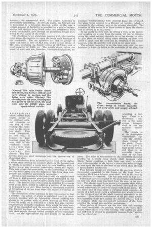
The final drive is also by open tubular shaft with HardySpicer joints at the front and rear. The casing for the rear axle is„,a steel casting containing an underslung worm and worm wheel, the worm shaft being carried on double taper roller bearings at the rear end and a plain single roller at the forward end, whilst the differential box and worm wheel are supported on double ball bearings, one pair taking the journal load and the other end thrust. Fully floating axle shafts are located at the wheel end, the inner ends being splined in the differential ; the shafts can therefore be withdrawn without dismantling the axle.
The drive is transmitted to the wheels by means of drivingcaps attached to the hubs, which in turn support the brake drums. Disc-type wheels are attached by separate bolts to the hubs, thereby enabling either the inner or outer wheel to be detached without disturbing the driving shafts or the brake drums.
Roth front and rear brake work call for special comment. The drums are a splendid jab, made from aluminium and lined with steel, the rear ones being no less than 5 ins, wide and well ribbed externally, in order to provide lateral strength. The shoes (of the internal-expanding type) are also of aluminium and are capable of separate adjustment iu the same way as are the transmission brake shoes. The brake operation within the front drums is by transverse -shaft with spherical joints above the centre lines of the pivots. The brake arms themselves are splitied on their shafts and any position far the lever can be obtained to give the correct setting for -the brake work.
A Dewandre vacuum servo motor is included in the system and is attached to the outside of the chassis, approximately in line with the gearbox. From the rear of the servo a rod runs to a. lever mounted on a cross-shaft, which is surrounded half-way across the chassis by another tubular cross-Shaft. These two elements are damped together at the centre which makes the operation for all four brakes emanate from the centre of the cross-shaft proper, and also serves the purpose of providing some measure of compensation between left-hand and right-hand brakes in pairs, due, of course, to the torsional spring in the tubular cross-shafts. Steel ribbons are used for the brake operation and are carefully guided in wood blocks in order to prevent rattle.
Semi-elliptic springs -are -fitted all round and are carried in substantial bearings held in aluminium alloy brackets. The rear springs are underslung and are fitted with overloading *leaves beneath the main body of the spring. The front springs are located on top of the axle and are inclined so that they take a certain proportion of horizontal shocks. Pour rebound plates and Houdaille shock absorbers combine to prevent bouncing.
With a capacity of 35 gallons of fuel, the petrol tank is three-point suspended at each side, by means of sheet steel brackets, which allow a certain amount, of flexing without coming any dead shock to the tank itself. The filler spont protrudes towards the off side of the vehicle and is easily accessible, whilst the underside of the tank is protected by gnard of the slat and .hannd types, similar to that used on the fuel tanks of all Daimler cars. The spare wheel is housced at the rear on a RUh-'5'2111C hung from the main frame. There 'is a tray upon which the wheel is mounted which can be slid out after releasing two clumps at the rear of the c-hassis.