


F OR 1928; Karrier Motors, Limited, of Huddersfield, has produced a
Page 50
Page 51
Page 52
Page 53
If you've noticed an error in this article please click here to report it so we can fix it.
new chassis which will undoubtedly arouse an extraordinary amount of interest at the coming Exhibition.
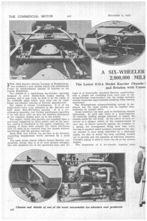
The chassis is a rigid-frame six-wheeler, specially designed to carry double-deck bodies seating 72 persons, and it may truly be said to be the result of the 2,000,000 miles which have been run by rigidframe, six-wheeled vehicles of Karrier manufacture. The engine is almost revolutionary. It is of the single-sleeve-valve type, designed by Mr. Ricardo and built under Burt-McCullum -patents, It is a six, cyfindered monobloc, but further particulars regarding it we will leave until we give the detailed description of the complete chassis later on in the article.
The engine, clutch and gearbox are mounted upon a sub-frame supported at three points, and as the gearbox control is bracketed to the engine crankcase, the undoing of three bolts permits the entire sub-frame with its units to be removed from the chassis without interfering with the gearbox controls.
Some little way behind the gearbox is an internalexpanding transmission brake operated by a hand lever.
The main frame closely follows former Karrier constructiOn„ except that it is of even greater strength: The side Members are of the spectacles type: and the bogie is of practically standard -Karrier construction, with a • torque rod extending from each axle to the spring-fulcrum cross-member, but the design includes certain important improvements resulting from running experience.
The Westinghousepressure-braking system is employed, but the same brakes can be applied independently by manual effort.
Great attention has been paid to facilitating chassis lubrication. At each side there is a large-capacity. oil reservoir holding enough lubricant to supply the chassis needs for one week, in the centre of each ,reservoir is a plunger which, at the commencement of each day, is drawn upwards against the pressure of a spring, the arrangement being such that every hearing is supplied under "pressure throughout the day, the amount to each being controlled by a discharge nipple, the size of which has -been carefully worked out to provide just the quantity of lubricant required. Petroflex piping is used to carry the oil to the various nipples.
The suspension of a six-wheeler -requires some
thought. It has been found that uncontrolled bogie movement causes a slight but rather disagreeable movement at the front end of the vehicle. With a view to obviating any vibration of this type pneumatic stabilizers are used in conjunction with the bogie axles, and the pressure for the stabilizer cylinders is obtained from the Westinghouse tanks.
We are not going fully into the details of the stabilizers, so we may as well describe them briefly here. The relative movement between the frame and each axle causes a piston to be moved in a cylinder, which is supplied with air at 100 lb. pressure. It will be realized that if. this piston, which is centralized, merely moved backwards and forwards in its cylinder it would alternately raise the pressure at each side of it and act as a cushioning device, but to give it a stabilizer effect the piston is equipped with opposed relief valves which allow a maxitnum pressure of 250 lb. only. Now, when the piston travels to either side, directly the pressure exceeds 250 lb. at the side towards which it is travelling, one of the valves opens and air flows through the piston to the other side; the aetion of shock absorption then ceases and stabilization commences.
It may be mentioned here that another use for the Westinghouse pressure tanks is for refilling the _tyres.
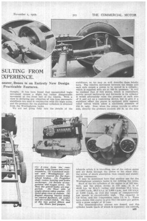
Each of the six cylinders of the engine is of 105 mm. bore, and the piston stroke is 150 mm. It is • of 40.09 h.p. by R.A.C. rating, and develbps 63.4 b.h.p. at 1,000 r.p.m, 98.5 b.11.o. at 1,600 r.p.ra., and 116 b.h.p. at 2,200 r.p.m.,„ so that the torque at comparatively low speeds is eXceptionally high. . The .capacity is 7.8 litres, and the compression ratio 5.3 to 1. Tests have shown this engine to give 73.5 tOn-miles per gallon with a gross weight of 10 tons.
The aluminium-alloy pistons are domed, anti thecylinder heads (each of which is separate) are conical, with the sparking-plug exactly ia the centre. 'Reaching over the W-hOle of the head is a -easing 'forming a. water-jacket. This is secured to the heads by means of the sparkingplug caps, and the single-sleeve valves work between two water-cooled surfaces just _around the ports, *here • the greatest heat is experienced..
The cylinders are, -of COITIn£, east„ but the heads are machined from bar steel.. 'The sleeves nate of :cast iron, because it has been featid that steed tneeves, whilst possibly permitting higher Fkpeetle, are apt inStnr.; DA a roattor of fact, the new Karrier engine can TM& up to speed.s of 3,000 The sleeves are operated by a layshaft, -upon Which worms are cut, driven h1 three Deralumiun eccentrics. Each :of these worms meshes with a -Worm wheel splined on in spindle carried in ball bearings. At the -end of this spindle is a Short crank running in a white-metal bearing of spherical shape, which is free to move in a lug -an -the sleeve., The hearing surfaces are ample, and the 7-43-hale gearing, which, incidentally, is of David. Brown manufacture., is permanently submerged in oil. The worm shaft runs in nine.bearings of white metal carried in bronze sleeves.
Ten hearings -of white metal in Phosphor-bronze shells are employed for the crankshaft, which is in halves with tke flywheel between the flanges -at the inner ends of the halves; the crankshaft and flywheel are spigoted together and secured by six bolts of three per cent. nickel-steal a driving fit into their boles. The flywheel is a steel stamping machined all over. It weighs 77 lh, without the starter ring. Its alt-nation in the centre of the crankshaft very creasiderably reduces torsional stresses and vibrations, and obviates bending stresses.
There sic two Separate exhaust manifolds connected to a Single pipe, and at the front and rear of the cylinders .are water-jacket covers provided with lugs to
facilitate lifting t h e cylinders.
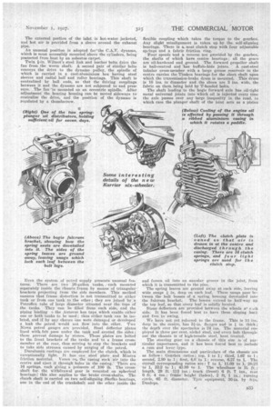
The housing for the special oil pump carries the two first bearings of the crankshaft. There are two plungers, these having -at their upper ends -eccentrics working on the crankshaft. The cylinders for the plungers can rock in the Casing, and it is this movement which opens and closes the suction and ;delivery ports. One
t34 plunger acts as a force-feed pump for the oil, the other is a sump scavenger.
The main oil tank is carried -on the roar dash. From it ail is supplied to the body of the pump through a port in the plunger cylinder, from w-hieh it is forced through another part into a pine leading to the worm shaft of the sleevedriving mechanism, which is hollow. Thence it passes to the main bearings and through holes in. the crankshaft to the big ends.
Splashed oil and vapour are relied upon for lubricating the sleeves and small ends. Oil overflowing from the worm shaft runs into the wells containing the worm gears, in whieh the level is kept constant by the provision of weirs between the wells. Oil scraped from the sleeves returns to the sump and is sucked out from this by the scavenging pump, which passes it through an oil cooler -consisting of a ribbed east-aluminium casing in halves and having a rotary paddle. From the cooler, the ail returns to the main tank, which Contains five gallons and is situated taider -the driver's seat.; on its way it has to pass a large filter, also secured to the -dash.
Thane are two relief valves, One for the general system, this being adjustable externally, and a high-pressure valve on the delivery side of the pump.
The drive to the magneto and centrifugal water pump is by a silent chain from the centre of the worm shaft. This chain requires Some form of adjustment, which is effected by rocking the magneto, tut this could not be dope if the magneto wore -driven in line with the pump; therefore, use is made of a novel form of coupling between the two. It consists of a chain meshing with two . sprockets slightly out of centre, and rocking the magneto platform does not alter the distance between the centres of these sprockets, but merely the relative positions of the centres.
The single gland of the pump is easily accessible. The water from it is taken direct to the rear of the easing for the cylinderheads and distributed all over these at an even temperature.
Carburation is effected by a Stromberg instrument. There is no induction pipe proper, the passages being partially in the cylinder walls and partially in a cover plate. Deflectors direct the mixture to each port. The external portion of the inlet is hot-water jacketed, and hot air is provided from a sleeve around the exhaust pipe.
An unusual position is adopted for'the C.A.V. dynamo, which is most accessibly mounted above the cylinders, being pr•tected from heat by an asbestos carpet.
Twin fin. Wilmot's steel link and leather belts drive the fan from the worm shaft. A second pair of similar belts conveys the drive to the dynamo pulley, the spindle of which is carried in a cast-aluminium box having steel sleeves and radial ball and roller bearings. This shaft is centralized by ball ends, so that the driving couplings between it and the dynamo are not subjected to end pressure. The fan 'is mounted on an eccentric spindle. After adjustment the bearing housing can be moved sideways to centralize the drive, and the position of the dynamo is regulated by a thumbscrew.
Even the system of petrol supply presents unusual features. There are two 20-gallon tanks, 2 each mounted separately inside the chassis frame by means of triangular brackets projecting from the side members. This method ensures that frame distortion is not transmitted to either tank or from one tank to the other ; they are joined by a Petrollex tube of large diameter situated near the tops of the tanks. They can be filled from each side, and the piping leading o the.Autovac has taps, which enable either one or both tanks to be used ; thus either tank can be isolated, and if by any chance One were damaged or developed a leak the petrol would not flow into the other. Two Nivex petrol gauges are provided. Steel deflector plates• lined with; felt pass under the tank and around the sides ; these prevent damage by stones. These plates are bolted to the. front brackets of the tanks and to a frame crossmember at the rear, thus serving to stay the -brackets and to take side stresses caused by surging of the petrol.
Duralurain castings are employed for the clutch, which is • exceptionally light. It has one steel plate and Mintex
• friction material. Vanes on. the easing suck air into the " centre and eject it through holes In the casing: There are 16 springs, each giving a pressure of 100 lb. The crossshaft for, the withdrawal gear is mounted on spherical bearings; this also applies to the -brake cross-shafts. The clutch shaftis carried on two self-aligning Skefko bearings, one in the end of the crankshaft and the other inside the flexible coupling which takes the torque to the gearbox. Any slight misalignment is taken up by the self-aligning bearings. There is anbat clutch stop with four adjustable swings and a fabric friction ring.
Four speeds and a reverse are provided by the gearbox. the shafts of which have centre bearings; all the gears are oil-hardened and ground. The forward propeller shaft
is ball-centred and has buffalo-hide joints. A cast-steel tubular cross-member with a large grease reservoir in the centre carries the Timken bearings for the short shaft upon which the transmission-brake drum is mounted. This drum is 16 ins, in diameter and the shoes are 3 ins, wide, the fabric on them being held by T-headed bolts.
The shaft leading to the bogie forward axle has oil-tight metal universal joints into which oil is injected every time the axle passes over any large inequality in the road, in which case the plunger shaft of the joint acts as a piston and forces oil into an annular groove in the joint, from which it is transmitted to the pins.
The spring leaves are ground away at each side, leaving wide snugs14, in. deep on each leaf. These suugs pass between the bolt bosses of a spring housing dovetailed into the fulcrum bracket. The bosses extend to half-way up the top leaf, so that every leaf is solidly located.
Stone deflectors are provided between the wheels at side. It has been found best to have these sloping back and free to swing.
We have not yet referred to the frame. This is 13 deepin the centre, has 5i-in. fltaiges and• is in. thick ; the depth over the spectacles is 24 ins. The material employed is .three per cent. nickel steel, and every bolt throughout the chassis is of high-tensile steel, heat treated.
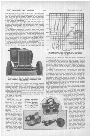
The steering gear on a chassis of this size is of particular importance, and it has been found best to include a cam and lever type.
ThO main dimensions and particulars of the chassis are as follow : Gearbox ratios : top, 1 to 1; third, 1.67 to I ; second; 2.80 to 1; first, 4„6 to 1; reverse, 6.27 to 1. The overall corresponding ratios are : 7 to 1, 11.69 to 3-, 20.23 to 1, 322 to 1; 43.89 to 1. The wheelbase is 11; ft.; length, 29 ft. 111 ins.; track (front) 6 ft. 7 ins., rear 6 ft. 4 ins.; frame. height (laden), 2 ft. 1 in.; turning. circle, 65 ft. diameter. Tyre equipment, 36-in. by 8-in. Dunlops.