


Patents Completed.
Page 22
If you've noticed an error in this article please click here to report it so we can fix it.
FRICTION GEAR. — l'attison and Another.—No. 3,377, dated February 12th, 1906.--The friction gear according to this invention adjusts itself automatically according to the load. The motor shaft (a) carries driving discs (b, the former being adjustable endwise under the control of rubber washers (z). A third disc (d) is free on the shaft (a), and between these discs transverse discs (e and 1) are mounted. The discs (e and fj are carried by transverse shafts, and controlled by screw-threaded sleeves (1, n) carrying sprocket wheels (1 and 2 respectively). These wheels transmit the motion of the discs to the wheels of the vehicle, but the discs themselves are each movable endwise on their supporting shafts against the action of a spring (y). It thus results that, as the road increases, the discs e and /) will be automatically advanced towards the shaft (a) against the action of the spring (y), but, as the load decreases, they will be returned by the springs, so that the speed of driving is accelerated. The discs (g and f) are idle.
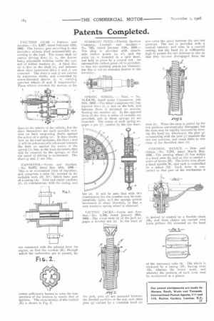
VAPORISER.—Evans and Another. —No. 10,972, dated May 10th, 1906.— This is an economical form of vaporiser, and comprises a tube (K) secured in detachable ends (11. H1), which form part of a casing (A). Inlet and outlet conduits (G, G) communicate with the casing, and
are connected with the exhaust from the engine, so that the conduit (K), through which the carburetter gas is passed, be comes sufficiently heated to raise the temperature of the mixture to nearly that of ignition. The cross-section of the conduit (K) is shown in Fig. 2.
SPARKING PLUG.—Electric Ignition Company, Limited, and Another.— No. 735, dated January 11th, 1906.— The plug is provided with detachable carbon points (a, al), and the point (a) is mounted in a split head, and held in place by a conical nut. An intermediate carbon point (a2) is provided, so that two sparking points are obtained, but this is not an essential feature to the invention.
SPRING WHEEL. — Noel. — No. 13,454/05, dated under Convention, July 10th, 1906.—The Wheel comprises two juxtaposed discs (tr, c) fast on the hub, and between these is mounted an annular floating rim member (a). In the opposed faces of the discs a series of recesses are provided, and in these springs (r) arc mounted. The centre of each spring engages a pin (f;, carried by the rim mem
her (a). It will be seen that with this construction the rim member may be comparatively light, and the springs permit movement in every direction, so that a very sensitive spring wheel is obtained.
LIFTING JACKS.—Lucas and Another.—No. 2,183, dated January 29th, 1906.—The screw stem (h} of the jack engages a divided nut (e). In the head of the jack, pins (f) are mounted between the divided portions of the nut, and other pins (z) carried by a rotatable head (a) also enter the space between the two nut portions. The nut is provided with a conical exterior, and rests in a conical seating, but the head (a) is sufficiently high to permit the nut portions to rise so that they become disengaged from the stem (h). When the stern is pulled up the nut portions automatically disengage, hut the stern may be rapidly returned by turning the head (a), whereupon the pins (g) co-operating with the pins (1) separate the two nut portions, and cause them to rise clear of the threaded stem (h).
CONTROL DEVICE. — Dew and ()thers.—No. 7,788, dated March 31st, l906.—The steering wheel (1) has within it a fixed stem (4), and on this is carried a series of levers (10). The levers turn about a fixed spindle (8), and each is controlled by a detent (12). Each lever is connected to that part of the mechanism it is desired to control by a flexible chain (14), and these chains are carried over loose pulleys (15) mounted on the head of the stationary tube (4). The whole is enclosed by a casing (l7), having slots (18), wherein the levers work, and whereby the position of each lever may be ascertained at a glance.