


A NEW HYDRAULIC
Page 58
Page 59
If you've noticed an error in this article please click here to report it so we can fix it.
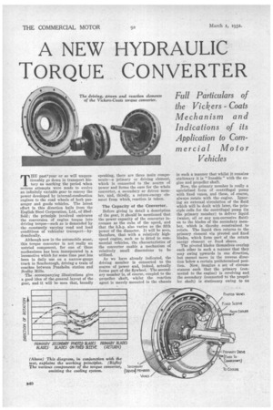
TORQUE CONVERTER THE pasttyear or so will unquestionably go down in transport history as marking the period when serious attempts were made to evolve an infinitely variable gear to convey the power developed by internal-combustion engines to the road wheels of both passenger and goods vehicles. The latest effort in this direction hails from the English Steel Corporation, Ltd., of Sheffield; the principle involved embraces the conversion of engine torque into driving torque—such as is demanded by the constantly varying road and load conditions of vehicular transport—hydraulically.
Although new in the automobile sense, this torque converter is not really an untried component, for one of these mechanisms has been incorporated in a locomotive which for some time past has been in daily use on a narrow-gauge track in Scarborough, driving a train of coaches between Peasholm station and Scalby Mills.
The accompanying illustrations give a good idea of the general layout of the gear, and it will be seen that, broadly speaking, there are three main components—a primary or driving element, which is connected to the source of power and forms the case for the whole converter, a secondary or driven member, and, thirdly, a return-energy element from which,. reaction is taken.
The Capacity of the Converter.
Before giving in detail a description of the gear, it should be mentioned that the power capacity of the converter increases as the cube of the speed, and that the blip. also varies as the fifth power of the diameter. It will be seen, therefore, that with a relatively highspeed engine, such as is fitted to commercial vehicles, the characteristics of the converter enable a mechanism of relatively small dimensions to be utilized.
As we have already indicated, the driving member is connected to the source of power and, indeed, actually forms part of the flywheel. The secondary member is, of course, coupled to the propeller, shaft, whilst the reaction agent is merely mounted in the chassis
in such a manner that whilst it remains stationary it is " lineable " with the engine and propeller shaft.
Now, the primary member is really a specialized form of centrifugal pump with fixed vanes, and these, of course, always rotate with the engine. Ignoring an external circulation of the fluid which will be dealt with later, the principle calls for the centrifugal pump (in the primary member) to deliver liquid (water, oil or any non-corrosive fluid) on to the blades of the secondary member, which is thereby constrained to rotate. The liquid then returns to the primary element via pivoted and fixed blades, which form part of the return energy element or fixed sleeve.
The pivoted blades themselves overlap each other in such a manner that they may swing upwards in one direction, but cannot move in the reverse direction below a certain predetermined position. Now, imagine a set of circumstances such that the primary (connected to the engine) is revolving and the secondary (connected to the propeller shaft) is stationary owing to an
excessive leak. The liquid would be expected to folloW the path denoted in the diagram by the full arrows because the seeondary component has no rotation value.
On the other hand, if the secondary be moving, the outgoing liquid has a velocity component in the direction of rotation of the secondary, so that if this (the secondary) be rotating at approximately half the speed of the primary, then the fluid will leave, approximately, in the direction shown by the dotted arrows, while the initial rows of pivoted blades will move into the dotted positions shown. The remaining rows of blades stay as they are and deflect the fluid back into the primary.
Importance of the Pivoted Blades.
These pivoted blades are of great importance to the successful operation of the converter, for without them there would be a great deal of agitation of the fluid, with consequent loss of efficiency. As it is, the blades adjust themselves as the load on the secondary varies (and its speed also varies), with the consequence that the fluid leaves it at varying angles. Once the speed is stabilized and the blades are under pressure in the line of the fluid motion they remain angularly stationary. It follows, then, that at all relative speeds of the primary and secondary the fluid enters the fixed element at the " easiest " angle, which,
of course, preserves the fluid energy and accounts for the increased torque.
Returning now to the point concerning the external circulation of the fluid as mentioned in one of the opening paragraphs. It will be noticed that two series of holes are drilled in the fixed sleeve, each series being connected to one of two unions. One series, forming the inlet, leads into the space in cornmunieation with the primary, whilst the other series of holes leads from the space from which the fluid leaves the circuit. There is a sufficient difference of pressure between the inlet and outlet to cause a circulation, and a form of fluid cooler can very readily be fixed up so as to maintain a reasonable temperature under all conditions of usage.
Although not shown in the illustrations, it is possible to arrange the mechanism with a friction clutch to Jock the primary and secondary together so that they rotate as a unit, for what may be called "top-gear transmission," and thereby obtain 100 per cent. efficiency, save for slight mechanical losses. The speed of the secondary may be equal to that of the primary, or anything between that speed and zero, and may vary with comparatively high efficiencies over a wide range.
The speed reduction of the secondary is accompanied by a corresponding torque multiplication, and it is claimed to have a maximum value of about 3.5 to 1. This action of torque multiplica
tion is quite automatic and Ismerely dependent upon the resistance encountered. The secondary may be stalled, due to overload, but the primary continues running, it seems rather doubtful, from the foregoing, whether a heavily laden vehicle could successfully negotiate a very steep incline without a greater engine-road-wheel reduction ratio than that provided in the rear axle. A two-speed auxiliary gearbox seems to be indicated.
When Power is Not Transmitted.
Owing to the characteristics a the converter (the power varies as the cube of the speed), it follows that, at "tickjug-Over" revolution speeds, the con, verter hardly transmits any power. at ' all; when it is desired to move off it is merely necessary to accelerate the engine, when the torque rapidly mounts up. So soon as sufficient road speed has been attained to correspond with the time when top gear would ordinarily be engaged in a vehicle embodying a normal type of gearbox, the locking clutch can be stripped into position.
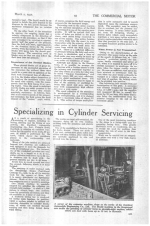
One interesting fact emerges from our investigation of this gear. A converter was recently designed to transmit 250 b.h.p. at 1,200 r.p.m., and the complete unit measured 25 ins, in overall diameter by 18 ins, long, this-latter dimension being the rneasurenient from the primary coupling to the end of the outermost gland.