


With Intent to Improve.
Page 20
If you've noticed an error in this article please click here to report it so we can fix it.
A Weekly Summary of Recent Patents, of Interest to the Maker and User of Commercial Motor Vehicles.
Selected and Abridged by H. S. Hall, A.M.I.A.E.
A New Bonnet Fastener.
Mr. H. H. Dixon, of Oakdene, Devonshire Road, Handsworth, Birmingham, describes in patent specification No. 103,347, of 1916,• a bonnet fastener invented by him, 1.1i hich would appear to be a considerable advance on any previous construction.
A bracket is attached to the bonnet board carrying, attached to it by a trunnion, a cylinder which serves as a r.eaincr for a coil spring. This spring bears at its lower end upon a plunger, the plunger being fitted at the top with a jaw end, and the latter takes hold of one extremity of a lever. This lever is fukrumed on a projection of the spring cylinder in such a manner that the spring always tends to pull the lever downwards and causes a projection on it to exert a downward pressure on a bracket riveted to the bonnet. It will be seen by reference to the illustration that practically the whole force of the spring is devoted to pressing the bonnet down into place. The leverage afforded to the hand lever for releasing this bonnet is so large that a spring considerably stronger than the usual type can be used for fastening the bonnet.
A Carburetter Improvement.
Mr. C. G. Grace, of Tregrayth, Ken wyn, Truro, in specification No. 11,830, of 1915, described a multi jet carburetter, the outstanding feature of which was that the number of jets in action could be varied in relation to the fuel required. This was accomplished by raising or lowering the jets. In No. 103,450, of 1916, ho describes an improvement upon this carburetter, whereby the admission of air is regulated to correspond with the number of jets in use. By reference to our drawings, which show a .side elevation and a section of this carburetter, it will be seen that within the float chamber and on a level with that of the petrol, is a plate drilled to accommodate a number of jets. Each jet is pierced by a hole at a certain distance above the bottom end. On no two jets is this distance the same. All the jets are carried by what is described as a sleeve valve capable of movement in co-operation with the throttle valve.
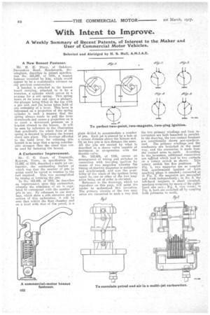
No. 102,606, of 1916, covers an arrangement of wiring and switches in connection with two-plug ignition by means of two magnetos whereby the timing oh the■two magnetost is automatic and synchronized, and also the possibility cif the whole of the ignition being upset by, one or other of the two magnetos being out of order is obviated.
Reference to the drawings, which e reproduce on this page, will assist the reader to understand this invention. The primary circuits of the two magnetos are connected in such a way that
the two primary Windings and their interrupters are both branched in parallel. In the drawing, the two contact breakers are intentionally shown non-synchronized. The primary windings and the condensers are branched in the usual way, and the oonne&ion is made from the contact arms to. earth. According to the invention, additional connections are applied which lead to two contacts
on a rotary switch as shown. This rotary switch has five positions. In Fig. 1, two magnetos are so coupled that synchronized ignition of both sparking plugs is ensured; connected as in Fig. 2, the magnetos are uncoupled and work independently; in No. 3, the left-band magneto is short circuited, sparking occurring by means of the righthand one only ; Fig. 4, vice versa; in Fig. 5, both are switched off by ceupling both primaries to earth.