


Patents Completed.
Page 16
If you've noticed an error in this article please click here to report it so we can fix it.
BODY.—Windham.—No. lo,388, dated May 17th, 1905.---The vehicle showp is a pleasure vehicle, but this invention may be applied to commercial vehicles. The body portion )C) is made to slide upon the chassis, and provided with detachable or collapsible legs (E) to receive it when it is removed rearwardly from the chassis.
For commercial vehicles the body part, stored with goods to be delivered, can thus be left at the place of delivery, and tither an empty body part taken up at the same place or the vehicle can return for another loaded body whilst the first body is being unloaded. The front seat (B) is secured to the chassis.
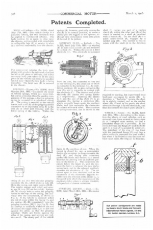
SPRINGS.—Houae.—No. 22,016, dated October 28th, 1905.—To absorb the recoil of vehicle springs, which is a more fruitful source of trouble than the sudden cornpression of the springs, a friction gripping device is mounted in a cylindrical casing (la The casing is secured to the vehicle frame, and a rod (8) of the gripping device connected by an adjustable strap (6) to the axle 171 or other part movable with the lower spring of the vehicle. Within the casing (1) are twa setni-circular gripping members (10, 11}, which slide on rods (23, 241 in the casing, and carry toggles (19,20. The toggles engage each other and enter an eye or loop (22) on the rod (8). Springs 131, 32) always tend to raise the gripping device to the top of the casing, but normally they are compressed, as shown in Fig, 2. If the vehicle is suddenly jolted the rod (8) rises within the casing It, arid the springs (31, 32) immediately raise the gripping members (10,11) (see Fig. 31; but an attempt to suddenly withdraw the rod (8i causes the toggle ends (c, 6) to jam one against the other, so that the gripping members (10,11). are forced against the sides of the casing, and prevent any cud. den recoil The steady pull of the vehicle
springs (9), however, gradually returns the rod (8) to its normal position, as under a steady pull the toggles do not operate, although they immediately come into action if the rod (8) be jerked.
IGNITION PLUG. — Bullock. — No,. 14,23, dated July 11th, 1905.—A winding (B) is built upon a core (A) and enclosed by a shell (1'). Within the core is a fixed electrode (('I. This electrode is insulated from the core, but connected to one end of the winding )E), the other end of which is connected to the terminal (G). An oscillating electrode (D) is also carried in the core (A), and is normally in contact with the electrode (C). The exterior end of the electrode (D) carries two spring blades (i, j respectively). Between the blades (i, :7) and the end of the shell (E) is an armature (E), having a projection (11), which normally. bears again the resilient blade, and thus maintains the electrodes in contact with each other. The armature is spring-controlled, and is shown in the figure in the position of rest. When the circuit is closed by, say, a commutator device, the armature is drawn towards the shell (F), and during this movement pushes the blade still further in a lateral direction by passing over an inclined portion of the'-blade (i). The projection (H) passes below the blade (i), and the mull-lent the latter is released the two blades spring back, and by the rebound suddenly separate the electrodes (C, D). The matured spark is thus obtained, and as the separation of the electrodes depends entirely upon the rebound of the blades (i, the speed with which the separation of the electrodes takes place is always constant, independent of current variations.
STARTING DEVICE. — Smit. — No. 6,061, dated March 29th, 1905.—The motor
shaft (I) carries one part of a ratchet clutch (3), whilst the other part (7) of the clutch is carried on a shaft (4) provided with a handle (8). On the shaft (4) is a quick screw-thread (9), engaged by a ratchet ring (10). The ratchet is free to rotate with the shaft (4) in the direction required for starting, but is prevented from backward movement by pawls (12). If, therefore, a " back-fire" occurs, the shaft (4) is slightly rotated, and as the ratchet wheel (10) is held by its pawls, the shaft advances through it by the thread (9), and thus disconnects the clutch parts (3 and 7).
WHEELS.—Amery.—No. 14,204, dated July 10th, 1905.—According to this invention the wheels of road vehicles, such an vans, have secured to thorn a tyre (b) of L-shaped cross section, so that a peripheral flange (b1) is provided. In the recess between the flange (61) and the bpdy part (b) R. ring (fi is secured by screws (c), The periphery of the ring (I; lies flush with the peripheral flange (M.), and thus a plain surface is presented for road traffic ; but when it is desired to run the same vehicle upon rails, the ring (f) is detached.