


Friction Drive For Engine Oil Pump
Page 42
If you've noticed an error in this article please click here to report it so we can fix it.
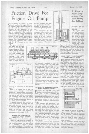
GEAR-TYPE oil pumps, as commonly employed in engine lubricating systems, impart a positive drive to the oil, and therefore variations in viscosity in the resistance of the system and in engine speed may give rise to undesirably high pressures. Usually a blow-off valve is incorporated as a safeguard, but a different method, claimed to have certain advantages, is shown in patent No. 548,500 by Morris Motors, Ltd., Engine& Branch, Courthouse Green, Coventry, and T. Brown and W. J. Thomas, of the same. address.
The pump consists of the usual pair of gear pinions (4 and 2), the former being the driver, but not directly attached to the shalt. Instead it is ' driven through the medium of a friction coupling. This cornprises a conical bore in the pinion (4) which engages an inner cone (3) forming an extension of the driving shaft.
Cone ,3 is driven by a pin (1) which passes through a slot, tilt's permitting up-and-down movement. A tension spring (5), stretched between this pin (1) and a lower one, supplies the engaging force for • the cones. Maximum drive is obviously limited by the torqueAratismitting ability of the clutch, thus constituted.
A second scheme is also described in which each pinion is divided into two half-width pinions, of which one pair is positively driven, whilst the other is rotated through the clutch. In the event of overload, half the pump continues to work, thus ensuring a minimum certain supply of oil.
MEANS FOR EQUALIZING INJECTION-PUMP OUTPUT
T"provide precise individual adjustment/for the respective elements of a multi-cylindered injection pump is the object of patent No. 548,457 by Z;. L. Stanley, '• Calvene," Wirks, wortli Road, Duffield. The rack-rod of the pump is divided into sections, one
to each plenger unit, and the specification describes a method of adjusting their relative lengthwise positioning.
The rack-pieces (3) are restrained from rotation on the rack rod (1). but each houses within it a sleeve, keyed to it by a circlip, which prevents relative axial fitovement (between, rack piece and sleeve), but permits rotation. The sleeves
are internally threaded to suit the screwed control rod (1), and have projecting ends (2) carrying notches or castellations which can be engaged by a special tool. By this _means they may be screwed along the control rod (1) and local adjustments effected in their linear positioning, and consequently, in the output of each element a " click " device serves to lock each sleeve against unwanted rotation.
' An advantage of the sehenie is that adjustments canbe carried out with the component in place and the engine running.
HYDRAULIC BRAKING SYSTEM WITH WARNING LIGHTS
DATENT • No. 548,279, from the Bendix Aviation Corporation, South Bend, Ind„ U.S.A.;. discloses an hydraulic braking system incorporating warning lights which come into action if the system should be in a state of unreadiness owing to loss of fluid. The master cylinder is also of novel design.
Two pistons are employed, the larger (6) being directly operated by the pedal, whilst the smaller (4) is minted by abutting on the larger one. Movement of the piston (8) to the left first closes the coned seating (8) and cuts off the connection (5) to the reservoir. Further -movement forces fluid thrddgh pipe 7 to the rear brakes. Meanwhile, the small piston first closes an inlet valve (2), after which the fluid is driven via pipe 11 to the front brakes.
A flexible partition (9) maintains pressure equilibrium between the two spaces, but does so only within the working limits. Should one side lose its fluid., the partition (9) would
maintain a seal and keep the other side in action.
The signal lights (1) are connected , to pressure-respon sive switches (10)
held in the off posi
tion by the slight pressure clue to the head of the fluid.
Should this dis appear the signal light would indicate which of the two sets had failed. • In order to keep the two fluid systems Vac separate for this purpose, the reservoir is also divided into two sections by a partition (3). The third light (12) is the pressureoperated standard stop-light.
GEAR PUMP FOR DURABILITY UNDER HEAVY DUTY
THE pumping unit of an hydraulic tipping gear is often subjected to high pressure, and must be not only leak-proof, but also of such construction that it is likely to remain so. Patent No. 548,494 discloses such a pufnp, the patentee being A. IL Alexander, of Alexanders of Edinburgh, Ltd., Semple Street, Edinburgh.
It will be seen that the pump is of the two-pinion type, and incorporates. a two-part casing comprising the body (1) and a cover-plate (2). The intersecting recesses which house the gears are of substantially uniform diameter for their whole length, including the bearing portion. The bearings, in one proposed design, are of the needle-rollet variety and have specially large outer races (4) to fit the casing.
The reason for this is to obtain 'a large, hardened precision-finished face to abut against the sides of the gears and to establish a durable leak-proof seal. The races (4) must each be provided with a flat at point 3 where, if they were circular, their peripheries would intersect.
In an alternative design the gears and their shafts are preferably, machined from the solid, in -order to ensure absolute concentricity, and may have plain bearings.