


Improved Swash-plate Engine
Page 70
If you've noticed an error in this article please click here to report it so we can fix it.
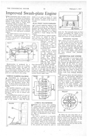
THE swash-plate ty'pe of engine seems to have an attraction for inventors, and regularly every year several patents appear on the subject. The latest, No. 762,777, comes from C. Clark, 24/25 Manchester Square, London, W.I.
According to this inventor, the mechanism for reVaining the wobble-plate is usually the weak point, and if this can be improved, the engine can compete successfully with high-speed crankshaft engines.
The engine shown in the drawing is a two-stroke, pressure-charged by a blower (1) via wall ports and exhausting via others shown at 2. A fuel injector is shown at 3.
Reciprocation is produced by a sloping groove in boss 4 as it rotates, but the , wobbler itself (5) must be restrained from rotating. This is done by a semi-circular stirrup (one end is shown at 6) which is pivoted at its midpoint on a pin fixed to the casing.
VEHICLE WASHING MACHINE
AMACHINE for facilitating the washing of buses and other large vehicles is shown in Patent No. 763,069 (R. Cox, 229 Broadway North, Walsall). It shows improved details on the design revealed in an earlier patent No. 692,005.
The machine comprises a tall rotary brush (1) encased in a spring loaded guard and fitted with a lever (2) for moving it into or out of contact with the vehicle.
The modifications consist of a pair of adjustable wheels (3) to prevent the brush being driven too hard against the side of the vehicle. Also, the brush slopes at an angle of about 15° from the vertical, the object being to allow the operative sections of the brush to overlap.
DUAL INLET VALVE PASSAGES
AN unusual induction scheme is disclosed in patent No. 763,081 (H. Weslake, Harbour Road, Rye Harbour, Sussex), the object being to improve the volumetric efficiency of an engine . by inducing a larger charge into the• cylinder.
The drawing shows a typical cylinderhead layout in which it will be seen that each inlet valve (1) is fed by a pair of passages (2 and 3). The two induction systems are brought out to separate carburetters, one on flange 4 and the other at 5, which has an exhaust heated hot-spot.
Control over several variable factors is given by the scheme; for example, the temperature of the charge can be varied by selective throttling from the hot and cold manifolds. Differing fuels may be used and their proportions determined by throttle settings.
Again, one carburetter may be set to give a rich mixture and the other a lean one, or one pipe may be allowed to pass air only. The scheme opens up interesting possibilities of testing these various factors under load.
BRICKS and certain other -building components cannot be off-loaded by tipping, and many vehicle-hours are wasted while hand unloading is performed. Patent No. 763,050, discloses a scheme by which this time can be saved. (a Hill, 32 Robindown Lane, Mansfield, Notts.)
The load is carried in a removable container (1) which normally rests on the vehicle frame. Hydraulic jacks (2) on the vehicle can raise the container by a few inches. While in the raised position, tubular legs (3) are then dropped to the ground and locked by pins in holes (4). The hydraulic jacks are then I lowered, permitting the vehicle to be driven away to make another journey while the bricks are being unloaded.
ROTATING VALVES TO rertove all restraint against rota tion of the valves is the aim of an assembly shown in patent No. 761,405. The usual spring-receiving collar is made separate from the ring that holds the split cones together, although they abut on polished faces. This allows the valve to turn slightly and even-out the wear. (Valves, Ltd., .Parkside, Coventry.) DIFFERENTIAL SLIP LIMITER
THE advantages of four-wheel drive incorporating a third differential are lost if one of the wheels is able to slip, because the differential gears will then allow all the drive to escape through the one wheel. A simple limiting device that will allow the differential to function at a slow rate but will not permit high slip, comes in patent No. 763,437 (The Rover Co., Ltd., Meteor Works, Lode Lane, Solihull, Birmingham).•
The drawing shows the unit which is built into a conventional differential assembly. • One of the output shafts is connected to the inner member (1) and the other to casing 2. The casing has a wavy bore which moves plungers (3) . mounted in the inner member. The plungers act as pumps, forcing liquid from one to the other via a central restriction.