


FORDSON TRACTOR TRANSMISSION GEAR.
Page 36
If you've noticed an error in this article please click here to report it so we can fix it.
A Resume of Recently Published Patents.
The trenemission gear of the wellknown Fordson tractor is described in some detail -in specification No. 130584. The inceptors state that their object ?s that of providing an improved transmission gear of :the type in which the clutch, gearbox, and final drive tmechanism are all enclosed within a common heusing; incidentally, as most of our readers are aware, the construction is such that this housing, combined ,with the engine crankcase, forms, in reality, the frame of the tractor, the front end of the engine • case being supported on the front -axle while the rear axle arms project from . the sides of this common housing to -which the specification makes reference.
The patentees further point out that they are confronted by the following somewhat conflicting conditions. Firstly, it is necessary, in order to permit of the use of road wlieels of ample diameter, that the axle itself be placed at a reasonable height from the base of the easing. Secondly, notwithstanding this position of the axle and differential case, it is necessary that efficient means be provided for lubricating the differential gear, and, thirdly, it is important that the centre of .gravity of the complete machine he kept as low as possible.
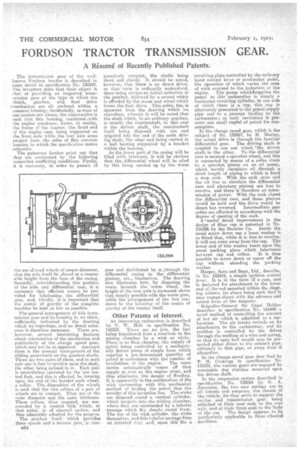
. The general arrangement of this transmission gear and its housing is, we think, sufficiently indicated by the drawing which we reproduce, and no detail reference is therefore necessary. There ,are, however, several interesting features about construction of the mechanism and particularly of the chan.ge speed gear, which may not be so apparent. Amongst them is the unusual arrangement of the 'sliding gearwheels on-the gearbox shafts. There are two pairs 6fthese, and in each pair one is free to revolve upon the shaft, the other being aplined to it. Each pair is nevertheless operated by the one control fork, and this is effected, by forming upon the end of the bo.es.Vof each wheel, a collar. The, disposition of the wheels is such that the two collars of a pair of wheels are in contact.. They are of the same diameter and the same thickness_ These collars,. tintsengaged, are surrounded by a control fork which, at that point, is of channel section, and thus admirably adapted foe +he purpose. The gearbox itself,which provides three speeds and a reverse gear, is rem
EM
paratively compact, the shafts being. short and sturdy. It should be noted, however, that there is no direct drive, as that tern is ordinarily understood, there being always an initial reduction in the gearbox, followed by a second which is afforded by•the worm and wheel which forms the final drive. This point, too; is apparent from the drawing which we itsproducc, wherein it will be noted that the shaft which, in an ordinary gearbox, is -many the countershaft, in this case is the driven shaft, the countershaft itself being disposed with one end spigoted into the end of the main driving shalt, the other end being carried in a ball bearing supported by a bracket within the housing. As the lower part of the easing will be filled with, lubricant, it will be obvious that the, differential wheel will be oiled by this being carried up by 'the worm
gear and distributed by it through the differential casing -to 'the differential pinions, etc., themselves. The drawing also, illustrates how, by disposing the worm beneath the worm wheel, the height of the rear axle. is increased above that usually possible with the worm gear, while the arrangement of the box conduces to the lowering of the centre of gravity of the tractor itself.
Other Patents of Interest.
An interesting carburetter is described by T. W. Holt in specification No. 155333. There are no jets, the fuel being transferred from a reservoir to the mixing chamber by a wick or wicks. There is no float chamber, the supply of petrol being controlled by a mechanically driven pump of simple form which supplies a pre-determined quantity of petrol in accordance with the number of revolutions of the engine. The same device automatically comes off that supply so soon as the engine stops, and thus eliminates the danger of flooding. It is apparently in the combination of the wick carburetter with this mechanical method of feeding the petrol that the novelty of this invention lies. The wicks are disposed ,round a vertical cylinder, which projects into the mixing chamber, where they are surrounded by a tubular passage which fits closely round them. The ton of the wick cylinder, the wicks themselves, and this t iihnlar passage form an inyerted ilorlo and, upon this fits a
revolving plate controlled by the ordinary hand control lever or acceieralor pedal, the operation of which varies the area of wick exposed to the induction of the engine. The pump whichtsupplies the petrol to this carburetter is simply a horizontal revolving cylinder, in one side of which there is a cup, this cup is alternately presented to the petrol supply pipe and to a passage leading to the carburetter ; at each revolution it presents one small cupful of petrol for consumption. In the change speed gear, which is the subject of No. 155367, by H. MoileY, the actual drive is through the familiar
differential gear. The driving shaft is coupled to one sun wheel, "the driven shaft to the other. To-the differential case is secured a sprocket -wheel, and this is connected by means of a roller chain to a sprocket pinion on an oil pump, which merely circulates oil through a short length of piping in which is fixed a stop cock. With the cock ,open and the oil free to circulate the differential case and planetary pinions are free to revolve, and there is therefore no transmission of power. With the cock closed the differential case, and those pinions would be held and. the drive would be direct but reversed. Intermediate gear ratios are afforded in accordance with the degree of opening of the cock. A ,useful detail improvement in the design of filter cap is patented in No. 155396 by the 'Daimler Co. Inside the usual screw down cap a loose washer is so fitted that, while it is .free to revolve, it will not come away from the cap. The lower end of this washer bears upon the usual packing piece which intervenes between cap and orifice. • It is thus possible to screw down or screw off the cap. without abrading the packing washer.
Harper, .Sons and 13ean, Ltd_ describe, Th No. 155419, a simple ignition control lever. It is in the form ol a pain, and is designed for attachment to the lower end of the•rod mounted within the steering column, its shape being such thatf it may engage direct with the advance and retard lever of the magneto.
'Brigadier-General Sir Capel Holden describes in Specification No. 155140 a novel method of controlling the amount of hot air which is admitted to a carburetter. The air intake swivels on its attachment to the carbhretter, and its position is controlled he the driver through the medium, of a wire and spring, so that its open bell mouth may be presented either direct to the exhaust pipe, obliquely to that pipe, or away from it altogether. In the change speed gear dese ibed by P. H. Cock-nags in sp-ecification No. 155331, the various gears are'engaged by concentric dog clutches mounted upcn the driven shaft.
In the suspension system described in specification No. 138064 by 0. A. Janemian, the two rear springs are to all intents and purposes, the chassis of the vehicle, for they serc'e to support the en'alue and transmission gear, being attached at their rear ends. to the rear. axle, and at their front ends to the body
of the car. The design appears to be particularly applicable to threeeeleeled • machines,