


Patents Completed.
Page 20
If you've noticed an error in this article please click here to report it so we can fix it.
Safety Valve ; Washer ; Radiator ; Ignition Device.
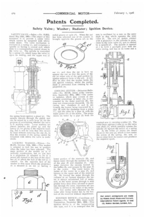
SAFETY VALVE.—Baker.---No. 10,912, dated May 25th, 1905.—The object of this invention is to provide a safety valve which cannot be tampered with whilst under steam. The valve mechanism is enclosed in a casing ((z., and comprises a spindle (c) having a conical end, which rests in a corresponding conical recess in the valve (e). The spindle is controlled by a spring (f), which keeps the valve (e) upon its seating, and the upper end of the spring bears against a gland (g). The spindle extends through the gland, and can be raised by a snift lever (d) for the purpose of ascertaining whether the valve is in working order. T.00se washers are plaeed between the gland (g) and the spring (f) for giving it the requisite loading, hut it will be seen that this cannot be done without removing the cap (b), so that the tension of the spring cannot be tampered with whilst the valve is under steam.
LOCKING WASIIER.-1Vilson.—N0. 20,571, October 11th, 1905.—This washer is adapted to lock the nut in position when the latter has been adjusted. The main portion of the washer (a) is of ordinary construction, but on one face is a projection (b) adapted to lie in a recess (d1) formed in the face of the member (d) in which the bolt of the nut (e) is carried. On the opposite face of the washer to that upon which the projection (b) is situated is an ear (c) having a radial groove or split (t1). When the nut has been adjusted one of its corners is brought opposite the groove (c1) in the ear (c), and then the ear is bent up against the nut so that the parts of the ear on either side of the split portion lie against adjacent faces of the nut. It will thus be seen that the washer holds the nut against rotation, whilst the washer itself is prevented from rotating by the projection (b).
COOLING SYSTEM.—Delaunay-Belleville.—No. 23,129, dated under convention, September 30th, 1905.—The cooler or radiator, which may consist of any suitable assemblage of tubes (A), is surrounded by the water reservoir (B), but does not communicate therewith. On the casing two chambers (1 and 2) are formed, the former being connected by a pipe (3) with the discharge from a pump (C), and the other by a pipe (4) with the water jacket (D) of the motor. The pump draws its water by a pipe (5) from the lower portion of the reservoir (B), and forces water through the radiator by way of the pipe (3) and chamber (1). This water traverses the circuits formed by the baffles (6), and escapes by the pipe (4) to the motor. The water leaves the jacket of the motor by a pipe (7), and returns to the upper end of the reservoir (B). By forcing the water through the radiator in an upward direction the latter is always maintained full of water, and, as the water passes through it with greater force than when allowed to gravitate through the same, impurities are less likely to adhere to the tubes of the radiator. Any earthy salts liberated by the water after being heated fall to the bottore of the reservoir without impediment.
IGNITION DEVICE.—Cornilleau and Another.—No. 14,318, 1905, dated under Convention, December 29th, 1904.—This ignition device is of the reciprocating arm type, and it is so arranged that the
arm is oscillated by a cam on the same shaft as that which operates the inlet valve (b). The arm (a) makes contact with a projection in the cylinder in proximity to the inlet valve (6), and is carried by a spindle (d). The spindle is tapered at i to form a gas-tight joint with the valve casing, and has at its lower end a cranked arm (c) carrying a roller (f). The roller bears against a earn CO on the valve cam shaft (h), which partially rotates the spindle (d) against the action of a spring 1/). As the roller (f) enters the recess shown in the cam (g), which it does under the action of the spring, the arm (a) moves away from its contact and produces the required spark.