


A Complete Analysis of How Chains Act.
Page 17
Page 18
Page 19
If you've noticed an error in this article please click here to report it so we can fix it.
Second Article : Roller and " Automatic " Gears.
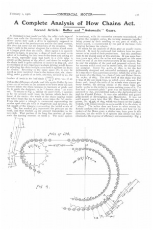
As indicated in last week's article, the roller chain type of drive now calls for illustration (Fig. 4). The inner circle driver shows how such a drive is commonly supposed to work ; but, as in the previous case and for the same reasons, this does not carry out the intentions of the designer. The larger circle is the correct diagram for a driver wheel made of a larger pitch than the chain. Here again it is scarcely possible to have, in practice, a slope of tooth so small as to admit of its holding its link close to the drum and taking all the strain, especially since that tooth in a cycle drive is always at the bottom of the wheel, and since the weight of the chain itself is quite sufficient to cause it to drop off. And no mechanic of any experience in chain driving would dream of adjusting the chain so tight as to hold it against the drum by tension. Reverting to the spare space (A), it may be noted as more restricted than in the former case, viz., something under 3-32nds of an inch, and this, divided by 22, the
number of teeth in the half-circle (0937-2-2 gives %)(4 of an
inch as the difference of pitch, and this again divided by two gives .002 of an inch as the amount to be worn away on each surface before the chain becomes in harmony of pitch, and fit, to quote the designer, to be " thrown away " as worn out. To return to Fig. 4, taking the outer circle, it appears to be the seventh tooth from the bottom which bears the brunt of the strain the whole of the chain lapping round the wheel from the top to tooth seven takes the full strain. From this point a triangle is constructed representing the strains upon that pin both in magnitude and direction, the full length of the triangle representing the initial strain of too. The line marked 58.5 represents the pressure on the tooth, and that marked 43 the amount transmitted to the next link. That portion of the long line marked 58 represents the turning moment on tooth 7. The same system is continued, with the successive amounts transmitted, and it gives the complete series, the turning moments together being proved by their totalling to too, part of which, as before stated, is counteracted by the pull of the loose chain hanging between the wheels.
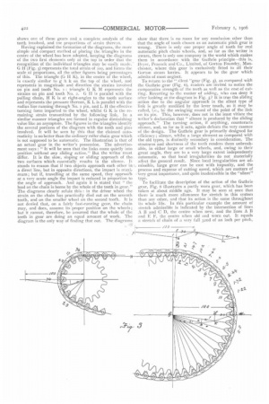
So much for the analysis of chain gear as usually manufactured. It must be confessed that makers have no great reason to be proud of their productions. And this statement leads to the crucial point of this analysis. It was some fourteen years ago, when the writer was engaged on this same work for one of the first manufacturers of the country, that he saw the mistake of the past and proposed reform ; but, for reasons which need not be stated here, the change was not accepted. Patent No. 4,160, of 1891, is for the first deliberately designed and successful automatic pitch gear. It is true there was a previous attempt, which the writer did not know of at the time, i.e., that of John and Robert Steele, No. 12,804, of 1885. The chief fault of this chain was that it was of the old block type, in which every alternate link drove, and, though the teeth of the wheels were almost perfectly formed, the driving blocks of the chain were very faulty : as far as the writer is aware nothing came of it. The first real " automatic pitch " gear was the Guthrie gear, as patented in 189T, and exhibited both at the Agricultural Hall and the Crystal Palace. It was also exhibited and gained gold Medals at Birmingham and Manchester. It was not until several years later that Mr. Hans Renold took out a patent, No. 24,346, of 1895, which was based on the Guthrie system, with improvements so as to entitle it to the claim of "silent." The writer does not know to what extent Mr. Renold analysed the action of these gears, nor how far the makers of the Morse gear, a similar one, have gone in this direction, but the writer is of opinion that silence has been obtained at the expense of efficiency and automaticity. Fig. 5
shows one of these gears and a complete analysis of the teeth involved, and toe proportions of strain therezm.
Having explained the formation of the diagrams, the more simple and compact method of placing the triangles in the centre of the wheel has been adopted, keeping the diagrams of the two first elements only at the top in order that the recognition of the individual triangles may be easily made; G H (Fig. 5) represents the total strain of ion, and forms the scale of proportions, all the other figures being percentages of this. The triangle (G H K), in the centre of the wheel, is exactly similar to g h k on the top of the wheel, and represents in magnitude and direction the strains involved on pin and tooth No. 1 : triangle G K M represents the strains on pin and tooth No. 2. G II is parallel with the pulling Chain, H K is at right-angles to the tooth surface and represents the pressure thereon, K L is parallel with the radius line running through No. I pin, and L H the effective turning force imparted to the wheel, whilst G K is the remaining strain transmitted by the following link. In a similar manner triangles are formed in regular diminishing value like an asymptote. The figures in the triangles identify the several portions of the diagram with the teeth and pins involved. It will be seen by this that the claimed automaticity is no better than the ordinary roller chain gear which is not supposed to be automatic. The illustration is that of an actual gear in the writer's possession. The advertisement says : " It will be seen that the links come quietly into position without any sliding action." But the writer must differ. It is the slow, sloping or sliding approach of the two surfaces which essentially results in the silence. It stands to reason that if two objects approach each other ht a direct line, but in opposite directions, the impact is maxi7 mum ; but if, travelling at the same speed, they approach at a very acute angle the impact is reduced in proportion to the angle of approach. And again it is stated that "the load on the chain is borne by the whole of the teeth in gear." The diagrams clearly refute this : in the driver wheel the strain on the chain has practically died out on the seventh tooth, and on the smaller wheel on the second tooth. It is not denied that, on a fairly fast-running gear, the chain may, and does, assume its proper position on the wheels; but it cannot, therefore, be assumed that the whole of the teeth in gear are doing an equal amount of work. The diagram is the only way of finding that out. The diagrams
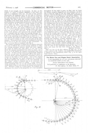
show that there is no room for any conclusion other than that the angle of tooth chosen as an automatic pitch gear is wrong. There is only one proper angle of tooth for real automatic pitch chain wheels, and, so far as the writer is aware, there is only one company in the world which makes them in accordance with the Guthrie principle—this is, Beyer, Peacock and Co., Limited, of Gorton Foundry, Manchester, where this gear is exclusively fitted to all their Gorton steam lorries. It appears to be the gear which admits of most neglect. To return to the " silent ''gear (Fig. 5), as compared with the Guthrie gear (Fig. 6), readers are invited to notice the comparative strength of the teeth as well as the cost of cutting. Reverting to the matter of siiding, who can deny it after looking at the diagram in Fig. 5? It is true the sliding action due to the angular approach in the silent type of link is greatly modified by the lever touch, as it may he i.e., by the swinging round of the point of the link on its pin. This, however, does not in the least vitiate the writer's declaration that " silence is produced by the sliding approach." The turning action, if anything, counteracts silence, and, so far as it acts, again defeats the very essence of the design. The Guthrie gear is primarily designed for efficiency; silence, whilst a large element as compared with the old types, is distinctly secondary in consideration. The stoutness and shortness of the teeth renders them unbreakable, in either large or small wheels, and, owing to their great angle, they are to a very large extent independently automatic, so that local irregularities do not materially affect the general result. Since local irregularities are admissible, large gear can be cast with impunity, and the process and expense of cutting saved, which are matters of very great importance, and quite inadmissible in the "silent" type.
To facilitate the description of the action of the Guthrie gear, Fig. 6 illustrates a partly worn gear, which has been taken at about middle age. it may be seen at once that there is much more allowance for stretch in this system than any other, and that its action is the same throughout its whole life. In this particular example the amount of stretch admissible is indicated by the intersection of lines A B and C D, the centre when new, and the lines A B and E F, the centre when old and worn out. It equals a stretch of chain of a very full 32nd of an inch per pitch, which, if not enough, can be increased. So that, on this system, if a gear is properly desikned it will work true until it is completely worn out. In most of the previous illustrations the diagrams have, for the sake of clearness, been kept away from the wheels; in the last two cases this has only been done for the first two teeth to enable readers to recognise the more ready and compact method shown in the middle of the wheel itself, the line G II being the scale which indicates, in magnitude and direction, the main strain. The triangle G H K, which is exactly similar to the one drawn above the wheel, represents the strains involved in pin and tooth No. t, and the triangle G K M, similar to J2 above the wheel, the strains involved in pin and tooth No. 2. G H is parallel with the pulling chain, and represents the too per cent, and scale. H K is at right angles to the tooth surface, and represents the pressure thereon. K L is parallel with the radius line running through No. t pin, and L lithe effective turning force on that tooth, whilst G K is the remaining strain carried on to tooth No. 2. In like manner the several triangles with like numbers represent the several strains on the teeth and pins of the same number. The general form of the curve produced by the lines H K M to G in the two systems is very remarkable. In Fig. 5 it is very flat as compared with Fig. 6.
For further comparison, in these last two figures numerals are used to indicate the several turning moments or effective turning pressures between wheel and chain opposite the points at which they take effect ; in the case of the driver the amount transmitted from wheel to chain, and in the case of the driven the amount transmitted from chain to wheel. If these several values be progressively deducted from the loo per cent, the remainder will ne the strain on the loose chain ; and the progressive remainders will be the strains on the chain at those points. And if these figures in the two diagrams are again compared the remarkable difference between the systems of the real automatic and the "silent"—which is claimed also to be automatic and distributive of strain—will be evident. :1 gear where the strain practically dies out on the second tooth, as in the small wheel of Fig. 5, can scarcely be claimed to be distributive. Whether a large or a small wheel, the Guthrie gear distributes the strain in the proportion of a true asymptote throughout all the teeth in gear; so that, now we know the system, complete diagrams are not necessary ; we have only to find the angle.of the first tooth which will be in harmony with the first figure in the asymptote, proportioned for the number of teeth involved, and all else follows. Of course, it may be observed that a chain is sooner worn out of pitch in a large wheel than in a small one, as indicated specially in Fig. 5, where N is the normal pitch line when the chain is new ; but the same amount of stretch has carried the working pitch line on the large wheel much higher up the tooth. Since the increase of pitch radius is in direct proportion to the increase of circumference or stretch, the design should be first made to suit the large wheel, with full allowance for the stretch of the whole life of the chain. At the time of the Guthrie patent the special form of link was designed to give a large wearing surface to the linkhead of the cheaper type of chain ; but this has nothing to do with the automaticity of the gear. The more expensive but better class of chain—viz., the roller type—is equally automatic, and that is the form (Fig. 6) which Beyer, Peacock and Company, Limited, habitually uses. A further advantage of adopting this type of chain is that each wheel can be independently designed to get the best result and angle of tooth ; whereas should such a chain as that shown in the Guthrie patent or the Renold or Morse be used the slope of the link-heads dominate the slope of all teeth, and cause the bad form shown in the pinion of
Fig. 5. HERBERT GUTHRIE.
The last line of the first column of page 405, in last week's article by Mr. Guthrie, was accidentally transposed : it should be read immediately below Fig. 3, in the righthand column.—En.]