


A New Form of Combustion Head
Page 70
If you've noticed an error in this article please click here to report it so we can fix it.
AN invention from such an authoritative source as J. and H. McLaren, Ltd., Leeds, merits the attention of all connected with the growing oil-engine industry, and patent No. 399,369 from the above concern deals with improvements in the form of cothbustion heads for direct-injection oil engines.
Hitherto it has been usual in this type of engine te inject the fuel towards or across the air-cell orifice. It is claimed that this method is unsatisfactory, in that it permits some.of the fuel to enter the air-cell during compression, which fuel is ignited later than the main charge, resulting in inefficient timing and knocking.
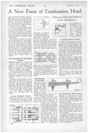
The invention is claimed to overcome these disadvantages by a novel arrangement of fuel and air jets. The illustration shows a plan view of a cylinder. The fuel is injected through a jet (1) and the air enters through two inclined orifices (6). These are arranged rather like the burner of an acetylene lamp, with the fuel jet mounted centrally. With this it is claimed that no fuel can possibly pass up the air-jets; furthermore, as all the jets converge to a common point, intimate mixing is attained.
Improvements in Cup-washer Pistons.
MODIFICATIONS in the-design of pistons, such as are used in the cylinders of servo mechanisms, usually applied to the power operation of brakes, are described by the Clayton Dewandre Company, Ltd., and Matt Payne, in specification No. 398,998.
This type of piston has a cup-washer used in conjunction with it, the object being for it to act as a seal in one direction, yet to allow fluid to pass with reasonable facility in the reverse direction.
Referring to the illustration, 11 is the piston body, having attached to it a cup-washer (4), which is supported firmly at its rear by a conical recess in the piston. The piston has a number of longitudinal slots cut in its periphery, which allow the fluid to flow past the piston, and past the cup-washer when it moves to the right. Any movement to the left, however, expands the washer, and effectually seals the cylinder.
Another Hydraulic Clutch.
WILLIAM MURPHY, Main Street, Randalstosvn, Northern Ireland, describes in patent No. 399,473 a form of variable-speed gear, working on a combination of hydraulic and epicydic principles.
In this invention the engine rotates a cylindrical member (3), having vanes (4) upon its periphery. Corresponding vanes are mounted upon the outer casing (1), which forms the driven member. A variable degree of coupling is obtained by sliding the driving member in an axial direction, which brings the two sets of vanes more or less into interaction. The driven member forms the spider (8), on which are mounted the planet pinions of an epicyclic gear, and a choice of ratios is afforded by braking one of the drums shown at 14.
A further clutch is shown at the rear of the gear, in the third drum (15). It appears to be difficult to see why three separate clutching devices should be needed.
Self-damping Leaf-springs.
AN ingenious and
simple modifieation of leaf-springs is shown in patent No. 399,341, from H. Burnand, 16, Rue Poyer, Crichy (Seine), Franc e. Its object is to introduce more friction to prevent prolonged oscillation of the springs.
It is a well-known fact that a free spring will, if deflected, start an oscillation which will persist until such time as its energy has been dissipated. To dissipate this energy is the object of so-called "shock absorbers," rebound dampers and similar devices; their basic principle is the application of frictioa to the spring movement.
This inventor proposes to introduce the desirable friction between the leaves of the spring itself. In its simplest form the ends of one or more leaves are doubled back upon themselves for a short distance, as shown in the drawing. Across this U-shaped end is placed a stirrup-shaped clamp containing an adjustment screw and lock-nut. By tightening this screw any desired amount of friction may be applied to exert a retarding influence upon the relative movement of the spring leaves.
An Easily Removed Piston.
A PISTON which can be removed from
above for replacement or decarbonizing forms the subject of patent No. 399,239, from Joseph Wakefield, 149, The Avenue, Tottenham, London, N.17.
The method of construction allows of the removal of the piston and its rings without disturbing the gudgeonpin assembly. This is achieved by making the piston in three pieces—the head portion (1), the skirt (4) and the gudgeon-pin housing (6).
The skirt consists of a tubular member with an interior shoulder (10). This shoulder is clamped between the head and the gudgeon-pin housing by screwed studs and nuts, the nuts being accessibly placed in recesses in the crown of the piston. In order to make a gas-tight joint these nuts are conical in the lower portion, and fit down into similarly shaped seatings in the piston head.
The advantage of being able to gain access to the rings, etc., without disturbing the cylinder block or big-end; is obvious.
FROM L. B. Kimball, 355, Central Avenue, New Haven, Conn., U.S.A., comes patent No. 399,198, disclosing a means for inter-mixing anti-knock fluid and fuel in certain proportions controlled by the engine.
This inventor claims that the usual mixture cannot be correct for all circumstances, and his invention consists of a control valve, operated by the exhaust pressure, which arranges the ratio of fuel to fluid to be made proportional to the gas flow through the exhaust manifold.
It appears rather difficult to see bow this method is superior to a simple constant mixture, which also provides a supply of anti-knock fluid proportional to the amount of fuel used, which is, of course, itself proportional to the exhaust-gas flow.