


Patents Completed.
Page 20
If you've noticed an error in this article please click here to report it so we can fix it.
Complete specifications of the following patents will be sent to any address in the United Kingdom upon receipt of eightpence per copy at the Sale Branch, Patent Office, Hoiborn, W.C.
LUBRICATION.—Hall and Mins.— No. 19,613, dated 22nd August. 1910.— This specification describes an adjustable overflow for the oil in the crank-charn
ber. A tube is externally screwthreaded at both ends with a right-hand thread at one end and a left-hand thread at the other. The middle portion of the tube is cut away to allow the oil to enter the tube and pass away to the reservoir. 'rhe lower end of the tube is screwed into a hole in the bottom of the crank-chamber, until the opening in the pipe is at the required level. The upper end of the tube, projecting through an opening in the Mill kcase. then has screwed upon it a nut which is locked by any suitable means.
STEAM WAGONS— C. Burrell and W. C. Wilson.—No. 20.738, dated 10th September, 1909.—This application has reference to the adaptation to a steam wagon of a method of driving the wheels, which has before been proposed for machines of another type. The steam engine is located on the top of the boiler, but the differential gear is arranged on the countershaft, and the use of a live axle is obviated by the adoption of a drive consisting of two side chains, one from each end of the layshaft, to spur pinions that are mounted on a crossshaft that is carried by two perchbars, which also act as radius rods. These perehbars are coupled to a dead axle. on the ends uf which are the road wheels provided with internal-toothed gear wheels to which the drive is transmitted by means of the spur pinions already mentioned. The wagon-chassis illustrated is provided with ordinary motor-vehicle front springing. instead of the single spring with a turntable and chain steermg gear, of the type which ;s more generally employed on traction t■pe of steam wagons and road locomoti% es.
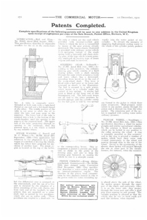
STEERING (;EAR. -McDonald— No. 17,707, dated 26th July. 1910.—According to this invention, the ordinary steering. gear which cnnsists of a fixed sloping pillar, with a shaft running through the same which actuates a worm and worm wheel, has a downwardextending lever keyed on to the end of the worm-wheel shaft. This lever is fitted with a ball joint at its lower end, arranged as shown in the illustration. The ball is encased in a split piston, which moves in a cylinder under the control of two springs. A similar ball joint is fitted Ht the front end of this transmission rod. The beRcrank levers are all tied to the other members by suitable springs, and the cylinder casing fir the ball joint is tied by two springs to the corresponding levers. This arrangement is stated to prevent any looseness or shake in the joints of the steering gear, and ahto to keep the steering gear balanced, so causing the vehicle to run in a straight course.
PISTON COOLING.—Krupp Aktiengesellschaft Germainaweift.—No. 15.216, 1910, date claimed under Convention 22nd November. 1909.—This specification describes a water-cooled piston for allinternal-eombustion engine. The chamber in the piston head communieates by two channels formed in ribs in the piston with two tubes extending up
wardly into the water jacket of the cylinder. To obviate the necessity of supplying high-pressure cooling water to the whole of the cylinder jacket, pockets are formed in the jacket in which these pipes reciprocate. High-pressure water enters in one packet. passes through the piston and is drained out from the other packet. The remaining part of the jacket is supplied with cooling water under ordinary pleasure.
PLOUGH WHEEL. — Staudinger.— No. 17.729, dated 26th July, 1910.—This specification describes a wheel for motor ploughs and similar agricultural vehicles. On the axletree is fitted an eccentric which can be locked in any position to the collar securing the wheel. A ring, is rotatably monnted on this eccentric, and to the ring is pivoted a number of spokes which have their outer ends twisted transversely to the wheel and passing through slots in the rim of the wheel. Owing to the eccentricity of the sheave, these spokes will project through the rim at some part of the circumference ; for instance, when the eccentric
is placed above the axle of the wheel,. the spokes project through the upper part of the wheel, and conversely, when it is on the lower side, they project through the lower part and offer a good grip when running on soft ground. The variable position is allowed so that the vehicle may he von on hard roads and such like surfaces, when required.