


The Specification and Testing of Motorcar Steels.
Page 14
Page 15
Page 16
If you've noticed an error in this article please click here to report it so we can fix it.
When a breakage occurs in any part of a chassis, me frequently hears the driver glibly speak of the fracture as being due to crystallization limier the influence of vibration. Perhaps it is, but experts in applied mechanics have for years been looking for examples of true cold crystallization; they would be glad to receive examples of fractures due to such causes, which examples would undoubtedly be placed in the museum of some scientific institution. Mysterious phenomena like cold crystallization seem to possess a great fascination fur some people; it is a much-more-polite thing to say that a crankshaft has broken due to crystallization than vulgarly to say it has broken as the result of bad driving, poor material or unintelligent design. Some manufacturers are pleased to have some mysterious phenomena to which they can charge their poor designing and the results of false economics practised in their purchasing departments. In almost every instance, these cases of so-called crystallization are evidences of metallic fatigue due to excessive and repeated stresses acting on badly-designed and ill-proportioned parts, which in many cases are also made of inferior material. Like a man of frail constitution, repeated and severe physical strain ultimately causes a collapse, whereas if his labour were less arduous his life might be a verylong one It is only by the application of dynamic tests to a piece of steel that we can ascertain its ability to bear sudden shocks or reversal of stress.
It has often been argued that. there is a great deal ol uncertainty attending the results obtained by impact testing. This may be because the metal below the notch has to bear the whole brunt of the blow or blows, whereas, in actual practice, anything in the nature of a notch, or groove, is avoided so far as the design will permit, and, therefore, all portions of the section are generally left free to sustain the load. It would appear that an impact test would be of more practical value were it made on the total cross section of a specimen. It seems practically certain that one isolated test will not afford sufficient data to enable accurate calculations of the steel's dynamic value to be made, but, if a number of repeated-impact tests were made on the same sample of material, the force of the blow being varied in each case, and the figures so obtained carefully compared with the results derived from tensile tests on bars from the same sample, a much-more reliable set of figures would be obtained. Neither the tensile test nor the impact test is completely satisfactory in itself, but when the two are taken in conjunction they may be made the basis of very-valuable and reliable conclusions. In itself, the registration of a large amount. of elongation during the tensile test of a specimen is not a true indication of the material's kinetic ability—the ability to resist repeated shocks, but it is fair to say that the absence of the property of elongation is invariably attended by inferior dynamic qualities.
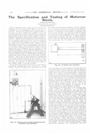
The relation of the elastic limit, to the working stress, whether constant or alternating, is a very-important matter, and we will endeavour to make this clear by giving the results of certain Wohler tests which have been carried out by John I. Thornycroft and Co., Ltd., at its Basingstoke works. We reproduce a photograph of the testing motor employed by that company. The Wiihler method has long been used for the testing of steels for axles, shafts and all other working parts in which the bending stress is being continually reversed. From the photograph (Fig. 14), and sketch (Fig. 15), which we reproduce, it will be seen that the specimen is gripped in a chuck, or coupling, on the armature spindle of a small electric motor, and, on the outer end of the specimen, a hall hearing is mounted. Suspended from this ball bearing, by means of a strap, is a definite weight. The bending moment on the specimen may easily be adjusted by varying the distance from the centre of the ball bearing to the face of the coupling, or by varying the amount of the suspended weight. Clipped to the test. specimen is a finger, which, as the specimen rotates, strikes a cyclometer star-wheel and records the number of revolutions made by the specimen. When the motor is running, it is obvious that the direction of the stress in every particle of the section is reversed twice per revolution of the armature spindle. As soon as the specimen breaks, it falls clear of the cyclometer, and, consequently, the latter
ceases to register. The number of revolutions made by a specimen before fracture occurs varies considerably with the brand of steel and the stress which is imposed upon it by the load. Take, for instance, the following two tests, in both cases the stress being well up to the elastic limit: a mild carbon-steel specimen made exactly 33,870 revolutions before breaking, whereas a piece nf
nickel
rl1IoIrle steel stood up to 381,800 before breaking. By making a series of such tests oil the same class of steel, under different rates of stress, it is possible to obtain a highly-accurate conception of the material's dynamic strength. It is probable, too, that by making a long series of such tests on the same brand of steel, and plotting the results, a definite relation between the "life" of the steel and its elastic limit might be deduced. The ratio is art inverse one, and the following figures clearly demonstrate the advisability of allowing a wide factor of safety on the elastic limit. In two tests made by Thornycroft's on specimens from the same bar of steel, the following results were obtained :— This goes to show that narrow margins of safety must be paid for at the expense of a short life.
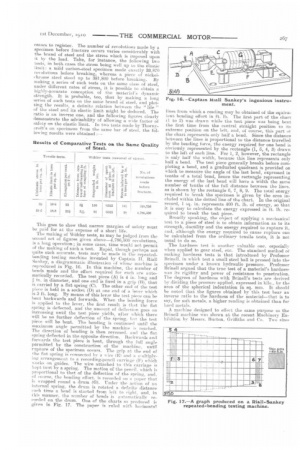
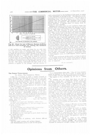
The making of Ubhler tests, as may be judged from the second set ot figures given above-4,786,500 revolutions, is it long operation; in some cases, time would not permit of the making of such a. test. Rapid, though perhaps not quite such accurate, tests may be made in the repeatedbending testing machine invented by Captain 11. Riall Sankey, a diagrammatic illustration of whose machine is reproduced in Fig. 16. In this machine, the number of bends made and the effort required for each are automatically recorded. The test piece (A) is 4 in. long and in. in diameter, and one end is fixed in a grip (11), that is carried by a flat spring (C). The other end of the test piece is held in a socket (D) at one end of a lever which is 3 ft. long. Ily means of this lever the test piece can be bent backwards and forwards. When the bending force is applied to the lever, the first result is that the flat spring is deflected, and the amount of defleetion goes on increasing until the test piece yields, after which there will be 110 further deflection of the spring. leit the test piece will be bent. Tho bending is continued until the maximum angle permitted by the machine is reached. The direction of bending is then reversed, and the flat, spring deflected in the opposite direction. Backwards and forwards the test piece is bent, through the full angle permitted by the construction of the machine, until rupture of the specimen occurs. The grip at the end of the flat spring is connected by a w ire (10.) and a multiplyMg arrangement to a recording-pencil carriage (if) which works on guides. The wire attached to this carriage is kept taut by a spring. The motion of the pencil. which is proportional to that of the deflection of the sprinit and. of course, the bending effort, is recorded on n paper that is wrapped round a drum (G). Under the action of an internal spring, the drum is rotated a definite distance each time a bend is started from left to right, and, in tins manner, the number of bends is automatically recorded on the drum. One of the charts so produced is given in Fig. 17. The paper is ruled with horizontel lines from which a reading may be obtained of the equivalent bending effort in ft. lb. The first part of the chart (1 to 2) was drawn while the test piece was being bent the first time from the central straight position to its extreme position on the left, and, of course, this part ot the chart represents only half a bend. Since the distance between the lines is proportional to the distance travelled by the bending force, the energy required for one bend is obviously represented by the rectangle (1, 5' 4, 3) drawn to the left of each line. For 1, 2, however, the rectangle is only half the width, because this line represents only half a bend. The test piece generally breaks before completing a bend, and a graduated quadrant is provided on which to measure the angle of the last bend, expressed in tenths of a total bend, hence the rectangle representing the energy of the last bend will have a width the same number of tenths of the full distance between the lines. as is shown by the rectangle 6, 7, 8, 9. The total energy required tobreak the specimen is given by the area included within the dotted line of the chart. in the original record, 1 sq. in. represents 400 ft. lb. of energy, so that it is easy to calculate the energy expressed in ft. lb. required to break the test piece.
Broadly speaking, the object of applying a mechanical test to a piece of steel is to obtain information as to its strength, ductility and the energy required to rupture it, and, although the energy required to cause rupture can be calculated from the ordinary tensile tests, it is not usual to do so.
The hardness test is another valuable one, especially when applied to gear steel, etc. The standard method of making hardness tests is that introduced by Professor Brinell, in which test a small steel ball is pressed into the specimen under a known hydraulic pressure. Professor 13rinell argued that the true test of a material's hardness was its rigidity and power of resistance to penetration. The degrees of hardness with Brinell's tests are derived by dividing the pressure applied, expressed in kilo., by the area of the spherical indentation in sq. mm, It should be noted that the figures obtained by this test bear an inverse ratio to the hardness of the material—that is to say, for soft metals, a higher reading is obtained than for hard metals.
A machine designed to effect the same purpose as the Brinell machine was shown at the recent Machinery Exhibition by Messrs. Burton, Griffiths and Co. Two sizes
a this machine are made, and these for use with balls of 5 aim. and 10 mm, in diameter respectively. lit each case, the ball is held in a hardened die, through a hole in which the ball prc.jects nearly one-half of its diameter. Behind the ball is a powerful and carefully-ealibrated spring of known rate. The piece of metal to be tested is placed upon the protruding ball, and a screw-operated plunger is then forced on to the top of the test piece until the latter is gripped between the plunger and the top ef the die. The spring underneath the hall yields as the pressure is applied by the plunger, and the impend if
yield is determined by the hardness of the metal, in which a clear impression of the ball is left. Thealiameter of this impression may be measured accurately, with the aid of a magnifying scale, .snd, by reference to a chart which is supplied with each machine, the hardness value of the specimen may be obtained. We reproduce one of these charts herewith. A special chart, of course, must. be plotted for each machine. Bending and torsion tests are also applied to steels, the simplest form of bending test being the placing of a test har on knife edges and loading it in the middle until it breaks. This test, however, is rarely used for steel, although it is the recognised one for east-iron arbitration bars. The torsion test is the last with which we intend to deal in the present article; its importance is frequently under-rated, bid, like the 'Wolder test, it is a particularly%altiable one and is especially applicable to such parts as motorcar crankshafts, gearshafts, driving axles, etc. In the making of this test, one end of a test bar is securely held in a coupling, and is prevented from rotating, whilst to the other end of the has a lever is fixed; by the application of a definite load at the end of the lever the bar is twisted beyond its Elastic limit. A piece of nickel-chrome steel 1 in. in diameter and S in. long, which, under the tensile test showed a maximum load of 58 tons per sq. in., an elastic limit of 45.6 tons per sq. in., an elongation of 19.5 per cent., and a reduction of area of 63.6 per cent., when tested for twisting, was given a permanent twist of 3.48 complete turns. or 1.252 degrees. before rupture oreurred.
In the next instalment of this article, we hope to give a list of suitable steels for the various parts used in a motor vehicle, and to give the complete specification of eaeh class of material.