


Better Steering for Three Wheelers
Page 58
If you've noticed an error in this article please click here to report it so we can fix it.
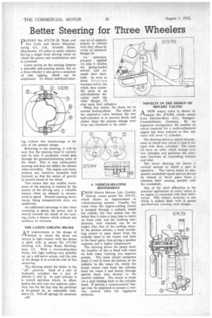
PATENT No. 673,758 (B. Wade and Dot Cycle and Motor Manufacturing Co., Ltd., Arundel Street, Manchester, 15) refers to small vehicles having a single front driving wheel on which the power and transmission unit is mounted.
Caster action on the steering imparts a desirable self-centring action, but on a three-wheeler it also gives a sensation of side tipping, which can be unpleasant. To obtain stabilized steer ing without this disadvantage is the aim of the present design.
Referring to the drawing, it will be seen that the steering head is vertical, and its axis, if projected, would pass through the ground-contacting point of the wheel. This is true centre-point steering and does not deflect the chassis when swivelled. The engine and transmission are, however, mounted well forward, so that the centre of gravity is located ahead of the wheel.
This means that any sudden movement of the steering is resisted by the inertia of the driving unit, a valuable feature when an obstacle is encountered at speed, Normal steering movements, being comparatively slow, are unaffected.
An additional advantage is that when cornering at speed, the power unit is moved towards the inside of the turning circler a feature which reduces any tendency to overturn.
THE LATEST GIRLING BRAKE A N improvement in the design of in• brakes in which the shoes are always in light contact with the drums is dealt with in patent No. 673,381 (Girling, Ltd., Kings Road, Birmingham, 11). With a two-leading-shoe brake, this light rubbing may possibly set up a self-servo action, and the aim of the design is to avoid the risk of this occurring.
The drawing shows the brake in the " off " position. Each of a pair of hydraulic cylinders has a pair of pistons (1 and 2). In each cylinder is a central partition which, in effect, makes the unit into two separate cylinders, but for the fact that the partition is by-passed by an adjustable leakvalve (3). Pull-off springs (4) maintain
A40 one set of opposite pistons in contact with their shoes by virtue of abutment flanges (5).
I n operation, pressure applied via pipe 6 reaches the spring-loaded pistons and expands their shoeends. As soon as drum friction becomes active, the whole shoe assembly turns in an anti-clockwise direction until the other flanges (7) abut upon their cylinders. When this occurs, the shoes act as normal leading-shoes. The object of the restrictive valve between the two half-cylinders is to prevent shock and clatter when the pistons change over from one abutment to the other.
A VEHICLE-HEATING REFINEMENT
FROM Morris Motors, Ltd., Cowley, Oxford, comes patent No. 674,351, which shows an improvement in vehicle-heating systems. Usually, hot water from the engine-cooling circuit is pumped through a radiator inside the vehicle, but this system has the defect that it takes a long time to warm up from cold, and the working temperature, once reached, can be no higher than that of the cooling water. In the present scheme, a local circulating system is used, direct from the cylinder head to the heater and back to the head again, thus giving a quicker response and a higher temperature.
The drawing shows the pump used; the impeller of this is fitted with vanes on both sides, forming two separate pumps. The main circuit comprises pipes (1 and 2) from the bottom of the radiator to the vanes (3), whilst the heater circuit runs from the cylinder head via vanes 4 and thence through special ducts (not shown) to the interior radiator. The return is made via a pipe leading back to the cylinder head. If desired a remote-control linkage may be employed to actuate a twoway control valve for regulation purposes. NOVELTY IN THE DESIGN OF ROTARY VALVES
ANEW rotary valve is shown in patent No. 673,994, which comes from Daimler-Benz A.G., StuttgartUntertOrkheim, Germany. By -an ingenious arrangement, the number of valves required for a multi-cylindered engine has been reduced so that one valve will cover I cylinders.
The drawing shows a typical arrangement in which two valves (1 and 2) are used with three cylinders. The ports (3) have an orbit which sweeps over two cylinders and performs the alternate functions of controlling exhaust and inlet.
The lower drawing (4) shows a vertical section in which a port is operative. The valves rotate at onequarter crankshaft speed and are driven by helical or bevel gears from a common shaft running parallel with the crankshaft.
One of the chief difficulties in The practical application of rotary Valves to an engine is concerned with their lubrication. This subject, however, is one which is seldom dealt with in patent specifications covering such designs.