


SENTINEL TRACTOR-LORRY TURNTABLE DESIGN.
Page 54
If you've noticed an error in this article please click here to report it so we can fix it.
A Resume of Recently Published Patents.
MHE number of designs for the attach ment between the tractor and trailer portions of a combination heavy vehicle w'ould seem already to be legion, yeli every 11431N and again a fresh one comes along and is deemed sufficiently novel to be given: a place in the archives at the Patent Office, and to be accepted by the authorities as worthy_of the grant of patent rights. The latest of these ideas is a sound and practicable one, standing to the credit of S. E. Alley, and it is described in patent specification No. 211,224.
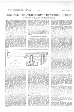
The object is the usual one, that of securing freedom of movement for the trailer with respect to the tractor—or 'vies versa—so that irregularities in the road surface may be negotiated without difficulty. In its most convenient form, and in the one illustrated on this page, the one portion of the turntable is rigidly secured to the forward end of the trailer, whilst the other part is attached to the tractor through this medium of spherical universal joiete and springs.
As shown in the accompanying drawe ing, the essential parts of the turntable proper are largely the same as those to which we are accustomed. The lower portion, which is the one carried by the tractor, is formed with a wide circular grove, shallow in its section, which is rectangular. A corresponding projection on the upper part of the turntable is designed to fit this groove, with which it actually engages. The two portions are properly secured together by a subetantial central bolt or king-pin.
Now, in this Alley design, the upper part of the turntable is carried by the trailer, as has already been staled ; it is, as a matter of fact, bolted to the frame of the trailer. The lower portion of! the turntable is supported by two vertical pins. These pins are ball-ended at the bottom, and rest in spherical housings bolted to the frame of the tractor. Provision is made, in the design of the housings, for the essential freedom of movement usually available to a
spherical joint. The turntable is not, however, rigidly secured, even to these ball-ended pillars, but is free to slide up nml down upon them. It i's restrained On that movement. by a pair of substantial coil springs, one to each pin„ and located-between the top of the turntable and nuts which are escesewed on to the upper ends of the aforementioned pillars.
rst will be gathered that this arrangement peimits of the necessary .lateral D60 swinging which takes place when the combined vehicle is traversing uneven stied surfaces. Fortiard knuckling of the machine at its joint is provided for by the ball joints of the supports of the lower portion of the turntable.
Another novel feature of this design is to be noted in reference to the comparative widths of the trailer and tractor frames. The farmer is much wider than the latter, thus providing the necessary clearance for this lateral sway, without the need for excessive height of the trailer.
Other Patents of Interest.
DESCRIBED in specification No. 211,256, is an invention by W. Foster and Co., Ltd., which is concerned with the means of connecting a tractor to an ordinary trailer, namely, by the use of a drawbar, and shows an improved construction whereby the negotiation of awkward corners may he facilitated. The drawbar is of the usual shape, that is to say, triangular, with its apex at Lashed to a fork at the rear centre of the tractor. Instead Of the base of this triangle being, as usual, hinged -to .the. front of the trailer, it is received between the upper and lower faces or • cheeks of a horizontal bracket or flap, which is itself pivoted to the trailer. When going straight ahead, the base of the triangular frame is temporarily secured within the cheeks by a pair of vertical pins or belts, which register with its earners. So located, the drawbar as a whole is the equivalent of any ordinary drawbar. Whenever it is necessary for the trailer to follow a curved path, one of the vertical bolts is taken out and moved to a new position, se that the drawbar swings round on to it, the base bar of the triangle 'taking up a position oblique to the front end of the trailer. With it so arranged, the tractor will exert a Pull which is at'an angle to the axis of the trailer, thus changing its direction.
CERTAIN modifications in the design
of his well-known thimble-tube type of .boiler are .described by Mr. T.' Clark son in speeification. Ices 211,342. The improvements indicated are intended tp make it more efficient as a utilizer of ,exhaust gases, the heat from which is used to boil the water in the
The cap of the boiler carries two branch pipes, one of which depends inside the nearly to the bottom; the other leads away at an angle to the first. The hot gases enter the boiler by one or Other 'of these pipes, and are thus compelled to traverse the whole of the thimbles before passing away to the atmosphere.
ONE important object of the c.arburet ter improvement which is described in specification No. 211,209, by Coinmercial Cars, Ltd., and E. W. Thomas, is the proVisioo of means whereby it may be possible, in certain throttle positions, materially to increase the proportion of fuel to air. Various methods of achieving this desirable, end have already been suggested, but this invention is partienlarly epplicable to carburetters which are designed to use gases generated from paraffin. The air-controlling valve and gas valve are both moved by a single rod, the two valves moving in unison during part of the range, while at one end the gas valve may continue to open after the air valve is opened to the ma:drawn and, at the other end of the range, the gas valve may be held •open to a given extent while the air valve continues to close. At each end of the range, therefore, the fuel mixture is enriched. The movement of each valve is limited by adjustable stops. The control engages the valves through the medium of springs, so that the valves move together until the stop of one of , them prevents its .f urtber motion.
THE device ,while is described in patent specification Nos 210,290, by P. Meikle, is really an elaboration of the exhaust pipe hot-ait muff. There are four pipes leading from the muffs one enters the induction pipe on the engine side of the throttle; another conummieates with the apace between cartniretter and throttle _valve, while a third op-ebs directly, on • to the 'mixing chamber itself. Each pipe embodies a stopcoeks and the proportion of hot air entering the induction via any one of the pipes is therefore independently controllable.
AN ingenious method of preventing the wheels from being locked by the application of a servo brake is described in specification No. 192,707, by F. Porsche. An important transmission lever of the brake gear is located on the front end of the spring-supported torque and thrust rod. If the wheels become locked, the rod moves back, carrying this lever With it, and reducing the leverage.
THE brake which is described in specie fication No. 211,262, by G. T. Hilton; is so designed that in the event of the mechanism failing the brakes automatic-, ally take effect. •There are a number of shoes sliding on radial bars. They are constantly being pressed towards the brake-drum surface, and are restrained by the brake gear.
A METHOD. of carrying the aerial far a wireless set ineide the hood of a car is described in specification No. 211A1, by N. H. Clough.
IN specification No. 206,807, I. R. Mail and Another describe an apparatus for electrically heating the explosive mixture, in or close to the carburetter.