


Patents Completed.
Page 28
If you've noticed an error in this article please click here to report it so we can fix it.
BALL BEARINGS.—Hoffmann Manufacturing Co., Ltd.—No. 19,790, dated 5th September, 1906,—The usual balls (a) are placed between the grooved tracks in the inner and outer rings (b, c), respectively, and the bearing is filled, with the exception of the space required for the cage, by the supplementary balls (d) These balls have diameters the same as those of the balls (a), but have flattened faces or sides, which enable them to be placed in the annular opening between the two rings (b, c) where they are held concentrically by the balls (a). They are then turned at right angles, so that they make contact, with their greater diameters, with the two grooved tracks, and take their part in carrying the load.
GOVERNORS. — Blackstone and Others.—No. 24,837, dated 5th November, 1906.—Pivotally mounted on the driving shaft (a) is a cam-shaped ring (b) having weights (d) attached at opposite corners.
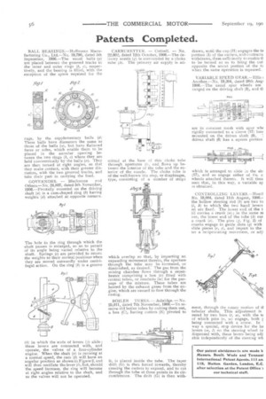
The hole in the ring through which the shaft passes is enlarged, so as to permit of its angle being varied relative to the shaft. Springs (e) are provided to return the weights to their normal positions when they are moved outwardly under centrifugal action. On the ring (b) is a groove (h ) in which the ends of levers Li) slide ; these levers are connected with, and operate, the valves of a four-cylinder engine. When the shaft (a) is running at a normal speed, the cant (b) will have an angular position as shown in Figure 2, and will thus oscillate the lever (i), but, should the speed increase, the ring will become at right angles relative to the shaft, and so the valves will not be operated. CARB U R ETT E R. — Cottrell. — No. 22,602, dated 12th October, 1906.—The delivery nozzle (g) is surrounded by a. choke tube (/t). The primary air supply is ad
mitted at the base of this choke tube through apertures (i), and flows up between the interior of the tube and the exterior of the nozzle. The choke tube is of the well.known iris stop, or diaphragm, type, consisting of a number of strips which overlap so that, by imparting an expanding movement thereto, the aperture through the tube may be increased, or diminished, as desired. T he gas from the mixing chamber flows through a superheater comprising a box (v) fitted with central tubes, or conduits (w) for the passage of the mixture. These tubes are heated by the exhaust gases from the engine, which are caused to flow through the casing.
BOILER TUBES. —Asbriclge. —No. 25,011, dated 7th November, 1906.—To remove old boiler tubes by cutting them out, a box (C), having cutters (E) pivoted to
it, is placed inside the tube. The taper drift (G) is thea forced inwards, thereby causing the cutters to expand, and to cut through the tube at three points in its circumference. The drift (G) is then with drawn, until the cup (H) engages the ta portion (I) of the cutters, and contracts withdraws, them sufficiently to enable ti to be turned so as to bring the cut. opposite the uncut portion of the tr when the same operation is repeated.
VARIABLE SPEED GEAR.—Ellis Another.—No. 19,204, dated 28th Augi 1906.—The usual spur wheels are ranged on the driving shaft (3), and a are in constant mesh with spur wht rigidly connected to a sleeve (17) loos mounted on the driven shaft (6). driven shaft (6) has a square portion
which is arranged to slide :ti the sle (17), and so engage either of thc s; wheels attached thereto. It will thus seen that, in this way, a variable sp is obtained.
CONTROLLING LEVERS.—Horcl No. 18,084, dated 11th August, 1908.– the hollow steering rod (b) are two to (i, k) to which the two hand levers 7a) are fixed. The lower end of the t (i) carries a crank (72) ; in the same ni ner, the lower end of the tube (h) car: a crank (a). The pins (25, Fig. 2) of cranks engage in guide slots (q) with slide pieces (r, a), and impart to the ter a reciprocating movement, or adji ment, through the rotary motion of ti tubular shafts. This adjustment is sured by two bars (1, a), with the te of which pins (v, w) engage, both y being connected with a screw. In way a special, stop device for the ha levers (m, 1) on the steering wheel (a dispensed with, these levers being adj. able independently of the steering wh