


A Hydraulic-powered Steering System
Page 60
If you've noticed an error in this article please click here to report it so we can fix it.
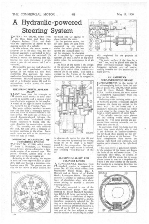
pA TEN T No. 635,483, comes from the 'Ross Gear and Tool Co., Lafayette, Indiana, U.S.A., and deals with the application • of power to the steering system of a vehicle.
In this scheme, the worm 1TM/es a follower (I) in the usual way, but the follower assembly is permitted to have a little, slack about the rock-shaft. (2) before it moves the steering arm (3). During this slack movement it pivots about a pin 14) and moves rod 5 of a
valve (6). • • _ The assembly does not rock about the pivot pin until pre-loaded centring springs . in the bosses (7) have been overcome; this . prevents the servo mechanism functioning on small steering movements. The valve controls the output of a hydraulic pump (8) and its accumulator, which power the servo cylinder (91.
THE SPRING WHEEL APPEARS AGAIN
X /IANY. have been the attempts to al absorb road shocks as near their, sourceas possible, and a sprung wheel has often been 'suggested in this respect.' A wheel of this type is shown in yatent ' No. 635,274 by G. Prechet, Pans.
The "main resilient members between huh and rim fake a telescopic tubular form (1), each of which contains a tension spring. On each side of these are • placed diamond-shaped linkages (the patent -calls them "articulated rhomboidal structures") biased into the open direction by compression springs (2). The assembly not only cushions the load, but also gives a measure of torsional resilience to the drive. Pneumatic tyres are said to be unnecessary with this type of wheel.
IMPROVING SCAVENGING OF TWO-STROKE ENGINE PkTENT No. 635,180, which comes from T. Nicholson, 33, Newfield Drive, Crewe, shows a design for a twostroke engine of an unusual type. The patent, however, applies only to the inlet valve for the scavenging air. -Referring to the drawing, the engine . is built up from opposed pairs of cylinders, each pair having a common combustion space (1). The pistons on one side do not move in exact unison, the
left-hand one (2) lagging in phase behind the other. In the position shown, the air inlet ports (3) have been uncovered by one _piston, whilst the other piston has opened the exhaust ports (4). At this moment, the charging air is supplied by a separate pumping cylinder (5); this is shown at top-deadcentre when the compression is at its greatest. _ The basis of the patent is the design of the air-inlet valve; this consists of a sleeve (6) in which slides a tubular extension (7) of the piston. The valve is worked by the friction of the sliding piston-nose inside it. and is stopped in its downwards motion by pins (8) and on the upstroke by meeting the seating flange (9) on to which it is fioally seated by the compression. No spring is needed, and rapid action is assured, thus avoiding " wire-drawing " of the air.
ALUMINIUM ALLOY FOR CYLINDER LINERS A CONSIDERABLE departure from PA standard practice is suggested in patent No. 635,156, which comes from Wellworthy Piston Rings, Ltd., J. Howlett and A. Stokes, all of Radial Works, Lymington, Hants. The patent discloses a scheme for making cylinder liners of aluminium alloy, with chromium plating to provide a durable wearing surface.
The alloy suggested is one of the aluminium-silicon group, that conforming to British Standard Specification B.S.S.L.33 being particularly suitable. This has a co-efficient of expansion of 0.00002-in, per degree C., and is, therefore, particularly adapted for fitting to a cast-iron cylinder block. The liner is internally chromium-plated to 'a' depth of up to 0.15 in. at least over that part of the liner subject to wear, and the surface of the plating is artifici ally, roughened for the holding oil.
purpose of
The outer surface, if the liner be 'a "wet" one, may be plated with zinc or other corrosion-resistant metal. The foregoing methods are, of course, equally suitable for the production of valve-sleeves.
AN AMERICAN SELF-ENERGIZING BRAKE IMPROVEMENTS in the design of
sel(-energizing brakes form the subject of patent No. 635,543, which comes from .R.' Hoyt, Duluth, Minnesota, U.S.A.. In this scheme, the servo action is transmitted .hydraulically from one
.shoe to the other.. .
Referring.to the drawing, when a pair of hydraulic pistons:(1) receives applied pressure, the shoes are spread in the usual Way. At the lower end is a seeondary hYdraulie cylinder (2) which is not piped to the system, but merely holds a small quantity of static fluid.
This cylinder contains outer pistons (3) and sliding within them, inner pistons (4). The outer pistons are prevented from moving outwards, but the inner ones can do so.
In operation, When the shoes meet the drum, they move slightly' with it, and if the direction be counter-clockwise, the left-hand shoe presses on the lefthand large piston at the bottouri. The fluid compression then moves the smaller right-hand one outwards, and applies extra ptesstire -to the right-hand shoe. • This extra-force is generated entirely by the rotationOf the drum, and forms the basis of -the self-servo action. The right-hand she 'tends, of course, to move also with the drum, but its upper piston comes to rest on a stop-face (5) which is the only anchor in the system. For motion in a clockwise direction, the same action occurs but in a reverse sense.