


Carburetter fol. Coal-dust Engines
Page 56
If you've noticed an error in this article please click here to report it so we can fix it.
ill.TCH research is proceeding in 1V1Germany into the possibilities of coal-dust as an engine fuel, and patent No. 502,922, from the Hanomag concern of Hannover-Linden, shows the latest practice in carburetting devices. The method outlined is to feed fuel into a chamber of whirling air, which is then fed to the engine while the turbulence persists.
In operation, air from the pump (4) passes a filter (3) and enters the mixing chamber via pipe 2. Coal-dust is continuously fed to the chamber, and the resulting mixture is blown from the nozzle (1) into the induction pipe.
To maintain turbulence, an excess of air is supplied, the surplus passing out of pipe 6 and into the induction pipe, a filter being fitted to prevent escape of fuel. This filter would rapidly choke, and an ingenious scheme is proposed to prevent this; a pair of rotary valves (5) are driven by the engine. and this causes pipes 6 and 2 to exchange their functions once per engine revolution, which keeps the filters continually blown clean.
Further details are given in another patent. No. 503,000.
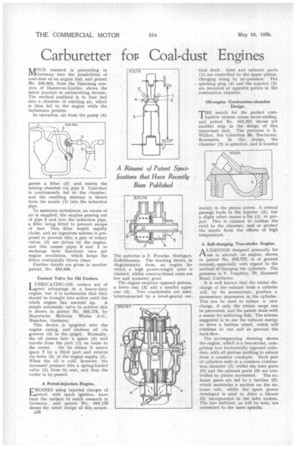
Control Valve for Oil Coolers.
LUBRICATING-OIL coolers are of great advantage in a heavy-duty engine, but it is undesirable that they should be brought into action until the
whole engine has warmed up. A simple automatic valve to achieve this is shown in patent No. 503,176, by Bayerische Motoren Werke A.G., Munchen, Germany.
This device is spigoted. into the engine casing, and receives oil via grooves (3) in the spigot. Normally, the oil passes into a space (4) and travels from the port (1) en route to the cooler. On its return it enters space 7 by a third port and returns via holes (6) to the engine supply (2). When the oil is cold, however, the increased pressure lifts a spring-loaded valve (5) from its seat, and thus the cooler is by-passed.
A Petrol-injection Engine.
ENGINES using injected charges of petrol, with spark ignition, have been the subject of much research in Germany, and patent No 503,173• shows the latest design of this nature.
A38 The patentee is F. Porsche, StuttgartZuffenhausen. The drawing shows, in diagrammatic form, an engine for which a high power-weight ratio is claimed, whilst constructional costs are low and economy good.
The engine employs opposed pistons, a lower one (3) and a smaller upper one (5). Two crankshafts are used, interconnected by a bevel-geared ver
tical shaft. inlet and exhaust ports (1) are controlled by the upper piston, charging being by air-pressure. The . sparking plug (4) and the injector (2) axe mounted at opposite points in the combustion chamber.
Oil-engine Combustion-chamber Design.
THE search for the perfect combustion system seems never-ending, and patent No. 503,201 shows yet another step in the design of this important unit. The patentee is E. Walker, Sos Colentina 88, Bucharest, Roumania. In this design, the chamber (2) is spherical, and is located
mainly in the piston crown. A conical passage leads to the injector (3), but a slight offset causes a lip (1) to project. This is claimed to confine the swirl to the chamber, and so protect the nozzle from the effects of high temperature.
A Self-charging Two-stroke Engine.
A LTHOUGH designed primarily for Pt use in aircraft, an engine, shown in patent No. 502,727, is of general interest,-especially with regard to the method of charging the cylinders. The patentee is F. Umpleby, 70, Harsnett Road, Cokhester.
It is well known that the initial discharge of the exhaust from a cylinder will, by its momentum, produce a momentary depression in the cylinder. This can he used to induce a new charge, if only the return surge can be prevented, and the patent deals with a means for achieving this. The scheme suggested is to use the exhaust energy to drive a turbine wheel, which will continue to run and so prevent the back-flow.
The accompanying drawing shows the engine, which is a two-stroke, comprising four horizontally opposed cylinders, with all pistons working in unison from a common crankpin. Each pair of cylinders ends in a common combustion chamber (1) whilst the inlet ports (3) and the exhaust ports (4) are controlled by piston movement. The exhaust gases are led to a turbine (5) which maintains a suction on the exhaust side, whilst the spare power developed is used to drive a blower (2) incorporated in the inlet system. The two turbines, as will be seen, are connected to -the same spindle.