


An Ingenious Rear-engine Design
Page 41
If you've noticed an error in this article please click here to report it so we can fix it.
Many Desirable Features in Unorthodox Layout Evolved by Ford Company. Observance of Practical Requirements Among Specially Noteworthy Mechanical Features
DESIGNERS of unconventional chassis layouts approach the problems facing them from a variety of angles, and great interest attaches to the different methods adopted. The rear-engine arrangement has shown itself to he one that attracts many inventors, although it involves the overcoming of a number of difficulties, and one of the cleverest schemes of this type that we have seen has recently come to our notice.
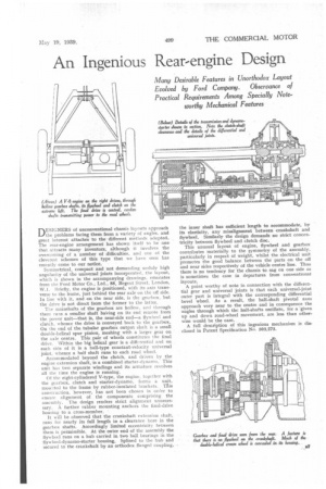
Symmetrical, compact and not demanding unduly high angularity of the universal joints incorporated, the layout, which is shown in the accompanying drawings, emanates from the Ford Motor Co., Ltd., 88; Regent Street, London, W.1. Briefly, the engine is positioned, with its axis transverse to the frame, just behind the rear axle on the off side. In line with it, and on the near side, is the gearbox, but the drive is not direct from the former to the latter.
The mainshafts of the gearbox are hollow, and through them runs a smaller shaft haVing on its end remote from the power unit—that is, the near-side end—a flywheel and clutch, whence the drive is conveyed back to the gearbox. On the end of the tubular gearbox output shaft is a small double-helical spur pinion, meshing with a larger gear on the axle centre. This pair of wheels constitutes the final drive. Within the big helical gear is a differential and on each side of it is a ball-type constant-velocity universal joint, whence a half shaft runs to each road wheel.
Accommodated beyond the clutch, and driven by the engine extension shaft, is a combined starter-dynamo. This unit has two separate windings and its armature revolves all the time the engine is running.
Of the eight-cylindered V-type, the engine, together with the gearbox, clutch and starter-dynamo, forms a unit, mounted to the frame by rubber-insulated brackets. TAis construction, however, has not been chosen in order to ensure alignment of the components comprising the assembly. The design renders strict alignment unnecessary. A further rubber mounting anchors the final-drive housing to a cross-member.
It will be observed that the crankshaft extension shaft runs for nearly its full length in a clearance bore in the gearbox shafts. Accordingly limited eccentricity between them is permissible. At the outer end of the assembly the flywheel runs on a hub carried in two ball bearings in the flywheel-dynamo-starter housing. Splined to the hub and secured to the crankshaft by an orthodox flanged coupling,
the inner shaft has sufficient length to accommodate, by its elasticity, any misalignment between crankshaft and flywheel. Similarly the design demands no strict concentricity between flywheel and clutch disc.
This unusual layout of engine, flywheel and gearbox contributes materially to the §yrnmetry of the assembly, particularly in respect of weight, whilst the electrical unit promotes the good balance between the parts on the off and near sides respectively of the vehicle centre line. Thus there is no tendency for the chassis to sag on one side as is sometimes the case in departures from conventional layouts.
A point worthy of note in connection with the differential gear and universal joints is that each universal-joint outer part is integral with the corresponding differential bevel wheel. As a result, the hall-shaft pivotal axes approach very near to the centre and in consequence the angles through which the half-shafts oscillate, for a -given up and down road-wheel movement, are less than otherwise would be the case.
A full description of this ingenious mechanism is disclosed in Patent Specification No503,273.