


THE LATEST OIL-E1 ;INED FOUR-TONNER
Page 50

Page 51
Page 52

If you've noticed an error in this article please click here to report it so we can fix it.
FOB. some time, Pagefield Commercial Vehicles, Ltd., Pagefleid Works, Wigan, has been devoting special attention to oil-engined chassis. We have already described various of its products and given an exhaustive road test of its 6-ton model, the performance of which was thoroughly satisfactory. A 4-ton chassis has been in production, but this has now been superseded by model FKG, which has forward control, four-wheel braking and a complete equipment specification. • The improvements have been effected without any increase in price.
The engine of the new machine is the 41-,9-type directinjection four-cvlindered compression-ignition unit made by L. Gardner and Sons, Ltd., Patricroft, Manchester. This engine needs no introduction to. our readers. The bore and stroke are 4i ins. and 6 ins, respectively and the engine develops a maximum of 50 b.h.p. In the FKGchassis a four-point mounting is employed. The two front suspension brackets pass over the frame and are bolted to it ; the engine feet are coupled to these brackets by spring-loaded bolts, thus giving a reasonable amount of vertical flexibility. The two rear points have no springs, but ties below them run from the engine to the main frame to take the torque.
The most interesting point about the engine mounting is that it is out of the vertical, being canted at about five degrees to the left, This is done to give increased room in the cab. Incidentally this principle avoids the need for offsetting the engine in the chassis frame;
in consequence the transmission shafts may be kept central and the universal joints can be kept in line longitudinally.
On the off side of the engine are the inlet and exhaust manifolds and the water puttm, whilst on the near side there are the belt-driven dynamo fuel pump and • governor, oil filler, filter and dipstick.. Above the , engine, and carried by the bonnet, is a subsidiary sixgallon fuel tank.This is fed from the main tank on the near side of the frame by. an Autopulse electric
.pump. . . In the flywheel is a 20-in, cone clutch of the threespring type, with a stop mounted on a special crossmember. The withdrawal mechanism has' ball bearings and -the drive to the gearbox is by a short shaft with two fabric univeral joints.
Two tubular bearers carry the gearbox, which is , suspended from them at three points. To the left of the driver is a gate control and there are two' -selectcir
shafts running back to the gearbox. One of these has an external locking device. The shaft below the gate has one bearing in a bracket attached to the engine, and one in a bracket on the frame ; both these bearings are self-aligning, so that relative motion between the engine and the frame causes no jamming of the gear control. A take-off for the speedometer, drive is incorporated in the gearbox lid.
IIardy-Spicer joints of 8-in, diameter are used at both ends of the tubular propeller shaft, which drives on overhead worm axle with a 41-to 1. ratio. This permits a governed speed of about 31 m.p.h. The axle has fully floating shafts and a horizontal banjo casing, both drive and torque being taken through the semielliptic springs, which have 11 leaves and are 3 ins. wide. When the chassis is unladen the spring length is 5 ft.
The front springs have 12 leaves, are 21 ins, wide and 3 ft. 5 ins, in length (unladen). In each case a four-bolt fixing is used for the spring, and in place of a centre bolt a band clip around the leaves registers in a slot in the spring palm of the axle. Both front and, rear springs are located from the front ends. Inclined steering pivots are employed on the II-section front axle, which is of the dropped-centre type.
This is one of the first chassis of its size to be equipped with the new Bendix cable-operated fourwheel-braking system. The shoes are internal expanding in all eases. The layout is unusually simple and solves many problems for the maintenance engineer and designer, whilst giving high efficiency.
From the pedal a rod runs to the distribution shaft, thence it continues inside the frame to a relay shaft and then the effort is transferred by enclosed cables to the camshaft levers. Bach brake has an individual adjustment turnbuckle and there is a master adjuster for each of the two gets. All these points are most accessible., The hand-brake rod is outside the frame and the final operation is by enclosed cables. The pedal takes effect/ on all four wheels, and the hand brak`e on the rear wheels.
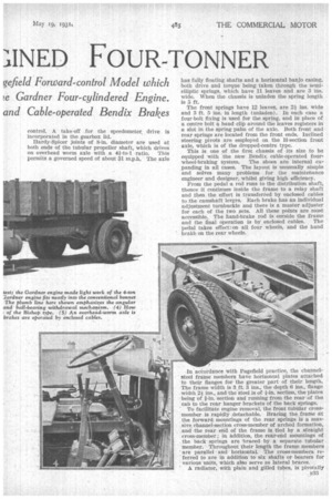
In accordance with PagefieId practice, the channelsteel frame members have horizontal plates attached 'to their flanges for the greater Ipart of their, length. The frame width is 3 ft. 3 ins., the depth 6 ins., flange . width 2* ins., and the steel is of fin. section, the plates
• being of f-in. section and running from the rear of the • cab to the rear hanger brackets of the back springs.
To facilitate engine removal, the front tubular crossmember is rapidly detachable. Bracing the frame at the forward mountings of the rear springs is a massive channel-section cross-member of arched formation, and the rear end of the frame is tied by a straight cross-member ; in addition, the rear-end mountings of • the back springs are braced by a separate tubular member. Throughout their length the frame members ' are parallel and horizontal. The cross-members re* ferred to are in addition to six shafts or bearers for various units, which also serve as lateral braces.
• A radiator, with plain and gilled tubes, is pivotally n33 mounted in split housings carried on the . dumbirons. No fan is provided, owing to the low working temperature of the oil engine. The radiator has a wide filler oPening to permit replenishment from a bucket.
• A special cross-member is provided to support the rear of the cab and to carry the rear ends of the front wings. The spare wheel is housed in the conventional position, behind the driving axle. Steel disc wheels carry 36-in. by 8-in. tFres, the rear tyres being dual. A full electric equipment is provided, and the headlamps are of the Lucas dipping variety. Bishop camtype steering is employed,, the column being conveniently raked and the wheel is well forward to give ample room to the driver.
The chassis which we inspected was of 15-ft. 10-in. . wheelbase, a noteworthy point being the small amount of rear overhang. The maker can offer a range of wheelbases to suit coachwork requirements.
On the occasion of our visit the first of these chassis , was undergoing its road test. The high final-drive ratio allowed the engine speed to be moderate at normal rates of travel, and the Gardiaer engine installed showed that considerable progress has been made in the silencing of oil engines from a mechanical point of view. The clutch took up• the drive sweetly and the new Bendix braking system proved to be powerful, without calling for any great physical effort.