


SUSPENSION OF ENGINE AND' TORQUE TUBE.
Page 68
If you've noticed an error in this article please click here to report it so we can fix it.
A Resum4 of Recently Published Patent Specifications.
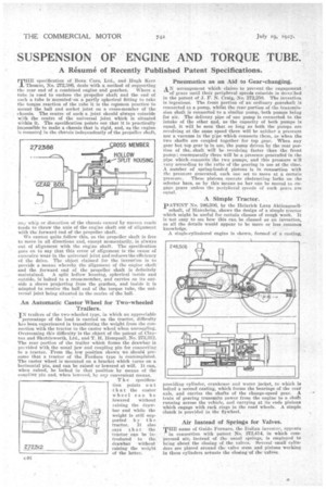
THE specification of Bean Cars, Ltd., and Thigh Kerr Thomas, No. 272,386, deals with a method of supporting the rear end of a combined engine and gearbox. Where a tnbe is used to enclose the propeller shaft and the end of such a tube is mounted-on a partly spherical fitting to take the torque reaction of the tube it is the co.mmon practice to mount the ball and socket joint on-a cross-member of the chassis. The centre of such, a joint should always coincide -vvtli the centre of the universal joint which is situated within it. The specification points out that it is practically impossible to make a chassis that is rigid, and, as the engine is moutiteLl in the chassis independently of the propeller shaft, • ey wl-dp or distortion of the chassis caused by uneven roads tends to throw the axis of the engine shaft out of alignment with the forward end of the propeller shaft.
We cannot quite follow this, as the propeller shaft is free to move in all directions and, except momentarily, is always Out of alignment with the engine shaft. The specification goes on to say that this error of alignment is the cause of excessive wear in the universal joint and reduces the efficieucy of the drive. • The object claimed for the invention is to provide a means whereby the alignment Of the engine shaft and the forward end of the propeller Shaft is definitely
maintained. A split hollow housing, spherical inside and outside, is bolted to a cross-member, and carries on its outside a .sleeve projecting irco-n the gearbox, and inside it is adapted th. receive the ball end of the torque tube, the universal joint being situated in the centre of the ball.
An Automatic Castor Wheel for Two-wheeled Trailers.
IN trailers of the two-wheeled type, in whith an appreciable . Percentage of the load is carried on the tractor, difficulty has been, experienced in transferring the weight from the connection with the tractor to the castor wheel when uncoupling. Overcoming this difficulty is the object of the patent of Clayton and Shuttleworth, Ltd., and T. H. Hempsall, No, 272,312. The rear portion of the trailer which_ forms the drawbar is prcvided with the usual jaw and coupling pin for connecting to a tractor. From the low position shown we should presume that a tractor of the ,Fordson type is contemplated. The castor wheel is mounted on a bracket which turns on a borisontal pin, and can be raised or lowered at will: It cars,when raised, he locked in that position' by means of the coupling Pin and, when lowered, by any convenient means.
T h e specification points o u t that the castor wheel can be lowered without raising the drawbar and while the weight is still supported by the tractor: It also says that the tractor can be introduced to the drawbar without raising the weight of the latter. Pneumatics as an Aid to Gear-changing.
_AN -arrangement which claims to prevent the engagement of gears until their peripheral speeds coincide is dereribed in the patent of J. F. N. Craig, No. 272,258. The invention is ingenious. The front portion of an ordinary gearshaft is connected to a pump, whilSt the tear portionof the transmission shaft is connected to a similar pump, both pumps being for air. The delivery pipe of one pump is conne.eted to the intake of the other and, as the capacity of both pumps is equal, it will be seen that so long as bah the pumps are revolving at the same speed therewill be neither a pressure nor a vacuum in the pipe which connects them, as when the two shafts are coupled together for top gear. When any gear but top gear is in use, the pump driven by the rear portion of the...shaft will be revolving faster than the front pump ; consequently there will be a pressure generated in the pipe whichconnects the two pumps, and this pressure VII vary according to the ratio of the gearing in use at the time. A number of ,spring-loaded pistons i,s in connectiou with the pressure generated, each one set to move at a certain
pressure. These pistons operate obstructing locks, on the selector bars, so by this Means no bar can be moved to engage gears unless the peripheral speeds of Such gears are equal.
A Simple Tractor.
pATENT No. 246,506. by tbe Heinrich Lanz Aktiengesell
schaft, of Mannheim, shows the design of a simple tractor which mightbe useful for certain classes of rough work. it is not easy to see how this can be classed as an invention, as all the details would appear to be more or less common knowledge.
A single-cylindered engine is shown, formed of a casting,
providing cylinder, crankcase' and water jacket, to which is bolted a ,second casting, which forms the bearings of the rear axle, and carries the shafts of the change-speed gear. A train of .gearing transmits power front the engine to a shaft running across the vehicle, and carrying at its ends pinions which engage with rack rings in the road wheels. A simple Clutch is provided inthe flywheel.
Air Instead of Springs for :Valves. . .
Tim name of Guido Fornacta, the Italian inventor, appears . in connection with -patent No. 272,414, in which cornpressed air, instead of the usual .springs, is employed to bring about the closing of the valves. Several -small Cylinders are placed around the valve stem arid pistons working, in these cylinders actuate the closing-of the valves.