


THE LATEST DORMAN OIL ENGINES IN PRODUCTION
Page 34
Page 35
Page 36
If you've noticed an error in this article please click here to report it so we can fix it.
A Review of the New Four and Six-cylindered Types—Their Construction and Performance Characteristics Fully Described
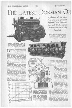
DORMAN petrol-paraffin engines have been known to the trade and, in a good many instances, to private owners of pleasure cars, commercial vehicles and power boats, for alrqost as long as the automobile industry has been in existence. Small wonder, then, that when the DormanRicardo range of compression-ignition engines was introduced recently they quickly aroused interest among operators and manufacturers of commercial vehicles alike.
During the past few weeks two new types of oil engine have been introduced and are in production. One is a six-cylindered unit developing 108 b.h.p., suitable for the largest types of bus and freight chassis, whilst the other is a four-cylindered model giving a maximum b.h.p. of 50, and intended primarily for vehicles of moderate size and carrying capacity.
Although, naturally, each type has its own special characteristics, the same high quality of niaterial and finish is to be found in both designs, whilst such an essential feature as robustness
is apparent in every detail. Notwithstanding their sturdy construction, the weights are not unduly high, the sixcylindered engine scaling approximately 13 cwt. and the four-cylindered model
being about half this weight.
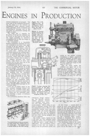
We will deal first with the larger engine. As will be seen from the performance graphs the unit runs up to 2,000 r.p.m., at which point the power curve is
s till rising, aIthoough naturally the torque and b.m.e.p. curves have fallen sothewhat, but, it should be noted, not to any marked extent. Maximum torque and minimum fuel consumption occur at approximately similar speeds, namely, around 1,200 r.p.m,, so that for roadtransport purposes t h e characteristics are almost ideal. With bore and stroke dimensions of 115 mm. and 130 mm. respectively, the swept volume works out at 8.102 litres—a moderate figure for such a powerful unit.
There are several features in the design calling for comment. The cylinders and the upper portion of the crankcase are cast as a unit, making a stiff foundation around which the various components are grouped. The lower half of the crankcase incorporating the sump is in two sections—an arrangement which enhances accessibility, especially of the crankshaft and connecting-rod bearings, and as the two parts are aluminium castings the weight is small.
The sump has a capacity for 44 gallons of oil and the container can be located at the front or rear end of the engine according to whichever arrangement fits in with the design of a particular chassis.
The crankshaft is a beautifully finished component, machined all over, and mounted in no fewer than eight bearings of 3i ins. diameter. All the auxiliaries are driven from a train of helical spur gears at the rear end of the power unit. Meshing with the crankshaft pinion is the camshaft gear ; there is a second pinion on the camshaft to drive the fuel pump and the exhauster, whilst from the camshaft wheel itself a further drive is taken to the dynamo, governor and water pump. The layout of these components will be seen from one of the accompanying illustrations.
Lubrication for all the major journals is, of course, effected by a full pressure system. The pump is carried just below the crankshaft, the drive being obtained by means of a helical gear meshing with the crankshaft pinion. Drawing from a circular filter in the sump, measuring no less than 9i ins, diameter and 4i ins, deep, the pump delivers to a main gallery attached to the crankshaft mainbearing caps, the big-end journals of the connecting rods receiving their supply through drilled passages in the crankshaft itself.
Leads are, of course, taken to the four camshaft bearings whence two pipes feed the overhead rocker gear, the tips of the rockers in contact with the valves and the ball-ended pushrods receiving a supply of lubricant under pressure.
The combustion chambers follow the well-known design embracing the Ricardo patents. Oblique passages connect with spherical swirl chambers into which pintle-type nozzles project. Heater plugs are provided to facilitate starting from cold. The compression ratio is 154 to 1. Aluminium-alloy pistons fitted with three pressure rings, one scraper ring above the gudgeon pin and alt additional scraper ring on the skirt, are employed and have fully floating gudgeon pins of 14 in. diameter.
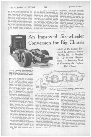
The smaller engine, known as the 4 DS type, has four cylinders bored to 90 n.m., which, with a piston stroke of 120 mm., give a swept volume of 3.063 litres. The performance characteristics of this unit are similar to those of the six-cylindered model, but 1.750
k owing to the smaller cylinder dimensions a higher crankshaft speed is obtained. At 2,500 r.p.m. the power curve still has a rising tendency, the power output being 50 b.h.p., whilst the torque at this speed is 106 lb.-ft.
Like the larger model, the cylinders and upper half of the crankcase are formed as a unit in a stiff well-ribbed casting. The sump, however, is in one piece with a capacity for 11 gallon of oil. Five main bearings of 21 ins. diameter support the crankshaft, all being fed with oil.
In this design a vertical shaft is driven by spiral gears from the camshaft, the gear-type pump being submerged in the oil in the sump. Two filters are incorporated, one on the suction side and the other on the pressure side of the pump, the latter being built on to the crankcase, where it works on the "constant bleed system" through a Tecalemit filter element. This system is also adopted on the sixcylindered model already described. The distribution drive to the auxiliaries is rather differently arranged on this model from on the "six." The gears are at the front of the engine and a belt drive is arranged for the dynamo, whilst another belt runs the water pump and fan, the former component being built into the forward part of the cylinder head. A helical spur pinion on the crankshaft drives the camshaft direct, and a second pinion on the camshaft transmits power to an additional wheel and shaft driving the fuel pump and the governor.
Like all compression-ignition engines in the Dorman range, vertically disposed overhead valves are employed•
and are operated by means of pushrods and rockers. The mounting for the rocker shaft is more than ordinarily interesting, for a hand lever attached to the end of the shaft enables this component to be oscillated through about 90 degrees, and, as the bearings are eccentrically arranged, it is possible, by moving the lever in one direction, to lift the inlet valves from their seatings (and so to cut out compression altogether), whilst, by moving it in the other, an excessive clearance is provided. Thus at low crankshaft speed during cranking the open valve dwell after bottom dead centre is eliminated and maximum compression pressure is assured. The running position is midway between the two extreme positions. The maximum cranking speed is obviously very low, so that practically no air inertia through the valves is developed. If desired a mechanically operated fuel pump, which is driven directly from the camshaft, can be supplied.