


A HUB WHICH LUBRICATES ITSELF.
Page 30
If you've noticed an error in this article please click here to report it so we can fix it.
A Resume of Recently Published Patent Specifications.
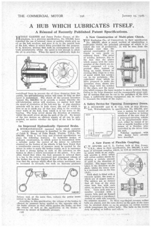
HENRY GARNER and James Parker Garner, of Birmingham, in a previous specification, No. 170,689, have described the use of internal vanes or paddles which pick up oil as the hub revolves, and pour it on to the central boss of the hub, where it enters holes provided for the purpose. It is, however, obvious that such an arrangement can only work satisfactorily whilst the speed is low enough to allow the oil to gravitate. When the speed is sufficiently high for
centrifugal force to prevent the oil from dropping from the paddle, the self-lubricating action will cease so long as that speed is maintained. The object of the 'present invention if patent No. 244,291) is to provide a means whereby the self-lubricating action will continue, no matter how high the speed of revolution of the hub may be. A pipe standing upwards will be seen in both views, the end of which is bent so as to catch any oil that may cling to the revolving inner walls of the hub, from which it is led down to the 'bearing. The large arrow shows the direction of rotation, whilst the small arrow shows the path of the oil. By means of the two devices an efficient supply of oil can be safeguarded, no matter whether the kpeed of the hub be high or low.
An Improved Hydraulically. Operated Brake. A HYDRAULICALLY operated brake which contains
certain new features is described in the specification of Caleb S. Bragg, of Palm Beach, Florida, U.S.A., No. 236,192. From a very long and involved specification we glean the following features. In hydraulic brakes of ordinary construction, in which power is transmitted from a cylinder under the control of the driver to cylinders situated on the brakes of the wheels, it has been found that a considerable amount of pressure must be exerted by the driver in order to apply the brakes evenly, as it is necessary to have a strong spring in each of the cylinders on the brakes to effect a return movement of the piston. It is also often found that when the foot pressure is relieved there is a lag in the return movement and consequent release of the brakes due to the frMtion of the oil in the pipes. It is true that the springs which effect the return movement may be increased in strength, but such an increase produces fatigue and, at the same time, reduces the power transmitted to the brakes.
According to this specification, the release of the brakes is effected by -pressure being applied to the opposite side of the brake pistons to that which applies the brake, so that the release as well as the application of the brakes is effected by means of hydraulic pressure.
c-16
A New Construction of Multi-plate Clutch,
THE Raybestos Co., of Connecticut, in their specification No. 244,825, show a novel method of constructing a multi-plate clutch, the principal advantage of which is to reduce the cost of production. It will be seen from the left-band view that the general construction of tle clutch is very much ou ordinary lines. The point of novelty, however, lies in the fact that the plates which engage with the outer member of the clutch are entirely composed o f compressed fibre, instead of being, as usual, formed by riveting fibre rings to a ring of metal which has notches cut in its periphery. The right-hand view, which we have prepared to make the invention clear, shows two fibre rings with the notches in the edges, and the metal ring which engages the inner member is shown between them Owing to the large diameter and the consequently great num ber of notches that can be cut in the periphery of the fibre rings, a sufficiently 'strong engagement can be relied upon to transmit the torque of the engine.
A Safety Device for Opening Emergency Doors, EJ. BUCKNEY and S. S. Guy, both of Guy Motors,
'Ltd., Wolverhampton, in specification No. 244,183, propose a system by means of which the latches or locking members of the rear door of a passenger-carrying vehicle can be simultaneously actuated, either by means of inside or outside handles or by means of a Bowden wire controlled by the driver from his seat.
Vehicles equipped with thN device have already been described.
A New Form of Flexible Coupling.
CW. SPICER and G. L. Tarbox, both of New Jersey, 'U.S.A., show in their specification, No. 244,307, a new form of universal coupling which, as well, as enabling shafts to rotate while at an angle, will provide a drive which will soften sudden shocks by allowing a certain amount of yield in the direction of rotation. The upper view is taken in the direction of the shaft, whilst the lower view is a sectional one on the line .(AA).
Each shaft is fitted with a two-arm spider, the arms of -which are of square section. The spiders are so formed that all four. of the arms come into line with each other, as shown in the lower view. Upon each arm is a member provided with a square hole and. so so formed that it presents a cup-shaped
surface at each side towards the adjacent member. In these cup-shaped recesses rubber balls are placed, and the nuts shown on the ends of the arms can be. screwed down so as to produce an initial tension which compresses the rubber balls". The balls do the double duty of acting as buffers and rollers.