


A Self-energizing
Page 72
If you've noticed an error in this article please click here to report it so we can fix it.
Brake
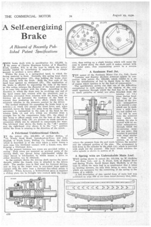
A Resume of Recently Published Patent Specifications THE brake dealt with in specification No. 331,979, in the name of Charles Montague Linley, of 9 Hamilton Road, London, N.5, is of the typo in which the power usually wasted by retardation is employed in a simple manner to produce a servo effect. Within the drum is a spring-steel band, to which the facing material is fixed. Normally this spring band closes on to the guide-pieces (G), thus holding the brake clear from contact with the drum. Both the free ends of the band hear against an abutment (F). The application of the brake is effected by separating the ends of the .band, as this action enlarges the diameter of the band and causes it to come into contact with the drum. According to the direction in which the drum may be revolving, one end of the band comes into contact with the abutment, and is, therefore, prevented from rotation with the drum, but the friction set up increases the tendency of the band to expand, thus producing the servo effect, which varies in constant relation to the pressure exerted by the driver.
The method employed for expanding the brake band is as follows :—A crank (E) parries the usual lever, and, when operated, moves the beam (C) away from the centre. This movement is transmitted to the ends of the band by the tension links (A and Al), which are diverted from a straight line by the compression links (B), the object of this being to afford ample room for the boss of the wheel. The compression links (B) are pivoted on studs carried on eccentrics Which can be adjusted to compensate for wear. The left-hand view shows the brake in the " off " position and the right-hand view shows it in the " on " position whilst the drum is rotating in the direction of the arrow.
A Frictional Unidirectional Clutch.
IN the patent (No. 331,905) of Arthur Bolton, of 13, Windy Nook Road, Gateshead-on-Tyne, and John English, of North Learn, Felling, Co. Durham, the clutch whieh is described is of the class where a screw forces a male cone into frictional contact with a female cone, thus forming a frictional drive. In the present instance two cones are provided within a casing. Both cones are mounted on screwed parts of the driving shaft, one thread being right-handed whilst the other thread is left-handed, by which means a drive in either direction can be obtained.
• In the example shown the driving shaft carries the screw threads, whilst the female cone is attached to the driven shaft. The smaller cone is that used for forward driving, and so long as the larger cone is prevented from making
• contact with the outer cone a forward free-wheel action is obtained. When, however, a bi-directional drive is required a slidink plate can be brought into contact with the larger cone, thus setting up a slight friction which will cause the cone to screw along the shaft until it makes contact with the outer cone, thus transmitting power in a reverse direction.
A Sunbeam Fuel Jet.
THE names of the Sunbeam Motor Car Co., Ltd., Louis
Coatalen and Stanley Herbert Attvvood■ appear in connection with patent No. 332,043, which relates to a jet for the introduction of fuel in liquid form to that class of engine where ignition is by the heat of compression.
The specification points out that one of the difficulties encountered in Such engines is the choking of the very small apertures through which the fuel has to be forced, as small particles of metal are often detached from the interior of t h e pipes during bending. One of the objects of the present arrangement is to provide a pipe which can be made from a solid forging and drilled out. s. As will be seen from the sectional view which we publish, the pipe is formed with an annular enlargement, through which the jet-carrying member can pass ; this member is provided with rings similar to those used in pistons, so as to elieve the pressure from the seal made between the member and the enlarged portion of the pipe. The arrangment is held down to the cylinder by the plate (A), which is provided with studs for the purpose. The lever which actuates the valve spindle is shown in section at B.
A Spring 'with an Unbreakable Main Leaf.
THE spring shown in patent No. 331,284, by W. Griffiths and Sons, Ltd., and A. E. Frost, both of Napier Steel and Spring Works, Savill Street East, Sheffield, is of the type in which the main leaf is so constructed that it takes no bending stresses, its only duty being to carry the eyes which are necessary for the connecting of the spring to the frame of a vehicle.
A full description of this special form of main leaf. was published on page 856 of our issue dated January 21st, 1930.