


A NEW METHOD OF CASE-HARDENING STEEL.
Page 70
If you've noticed an error in this article please click here to report it so we can fix it.
A Résumé of Recently Published Patent Specifications.
RHEINISCHE METALLIVAAREN UND MASCHINENFABRIK, of Dusseldorf-Derendorf, in specifications Nos. 242,978 and 244,431, describe a system of case-hardening steel which should be of interest to all connected with the production of motor parts. In this method, the usual process of cementation, heating steel in a receptacle packed with carbon, is carried out in the normal manner, the feature of the invention being in the method of reheating for quenching.
It is well recognized that, in casehardening, better res.ults can be obtained if the articles subjected to the process of cementation are allowed to cool and then reheated before quenching. The specification points out that the core, or part of the article to which the case-hardening has not penetrated, is not imProved in many cases by being quenched at a hardening temperature. In the case of mild-steel, the effect on the core is comparatively slight, but where high-grade and_ alloy steels are• employed, as in the parts of motorcars, quenching at hardening temperatures might not affect the limit of strength so much, but the elongation and toughness of the steel might be seriously reduced.
The feature of the invention lies in the fact that the article to be reheated for quenching is placed in a bath of melted metal, which raises the outer layer to hardening temperature before the heat has time to penetrate to the core, so that the core is not affected by the reheatins operation, and can be previously heat-treated, and the result of that treatment will be but little altered by the reheating process.
In one specification, the claim is made that the reheating only penetrates to a depth of less than the depth of the layer that has been effected by cementation, whilst in the later specification the claim is made that the reheating can be allowed to penetrate below the depth of the carburized layer.
Welding Ball-bearing Cages.
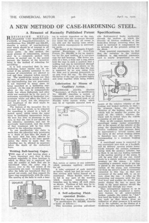
THE cage of a ball bearing plays a more important part than is often realized, especially in those bearings in which no filling slot is employed, and only the number of balls that can be introduced when the outer ring is thrown over to the full extent of its eccentricity are used. In such bearings, after the balls are introduced they are spread out evenly, and thus support the inner ring concentrically with the outer The spacing of the balls in such a bear lug is entirely dependent on the cage, and should that fail to operate through any cause the balls may all crowd to one side and the bearing come adrift, with serious consequences to surrounding parts.
The patent of the Compagnie d'Applications Mecaniques, of Ivry-Ports _France, No. 264,465, is for an apparatus for the spot welding of a two-piece cage for ball bearings. The device consists of a base, a stem and a cap, which hold the cage in such a position that a welding tool can be introduced through holes provided for it, as shown on the left, where it will be seen that the cage is supported by an arm rising from the base and is pressed downwards by an arm from the cap. By this means the halves of the cage are pressed tightly and truly together while being welded.
Lubrication by Means of Capillary Action.
GRAISSAGE ALCYL (Sod'Et( Anonyme), of Paris, in specification No. 259,567, describes a system of lubrication of such parts as those of motorcars from one central tank of oil. Flexible tubes enclose wicks, which may be of vegetable material such as flax, cotton or rattan or any substance which possesses capillary attraction for oil.
A tube, composed of such material
as cotton, which has had its surface covered with boiled linseed oil, is mentioned. These flexible tubes may be led to any part of the machine which requires lubrication, and branches may be taken off such pipes, as shown. Portions of felt may be inserted in hollows made for them as shown in the lower figure.
A Self-adjusting Fluidoperated Brake.
THE Fiat Societa Anonima, of Turin, in specification No. 255,906, describe a brake as follows:— This invention provides self-adjust able fluid-operated brake mechanism through the medium of which the decrease of friction coefficient of the brake-shoe linings occurring when the speed is increased is compensated by an increase of the pressure acting on the shoes.
From practical experiments we find that the variation in the friction coefficient in the material commonly used is nearly proportional to the square of the relative velocity of the braking and braked surfaces, so that— the pressure being the same—the efficiency of the braking action on a vehicle will be smaller the greater the speed of the vehicle, whereas the wheel will be locked when the vehicle is running at low speed.
Now, as the eiessure furnished by a centrifugal pump varies proportionally to the square of the velocity of the pump, the characteristic curves of the friction coefficient and pressure have an approximate'sinverse course, and the curve of the actual braking action is therefore very near to the curve corresponding to a constant braking action.
A centrifugal pump is connected to any convenient part such as a layehaft, and its delivery opening points downwards towards the passage communicating with the pressure cylinder, but as there is an opeeing leading upwards to the auction opening of the pump, it will be seen that oil can run round freely in a circuit without exerting any pressure on the piston. A valve, resembling a common water or gas tap, is placed in the opening leading to the suction of the pump, and connecting rod from the driver's pedal is constantly connected to this tap, so that any movement of the pedal will, to an extent, close the tap. A collar on the connecting rod connects with the vertical lever, and enables the driver, after partly closing the tap, to apply his brake in the usual manner should the pressure fail through any cause.
This arrangement appears to ne to lack what is now considered a necessary feature in all power-assisted brakes, namely, the power to " feel " 'how hard the brake is being applied. A tap such as that shown gives no indication of what pressure it is setting up in the cylinder, as the closing of a mushroom valve against a pressure does.