


A Five-speed Transmission for Buses
Page 66
If you've noticed an error in this article please click here to report it so we can fix it.
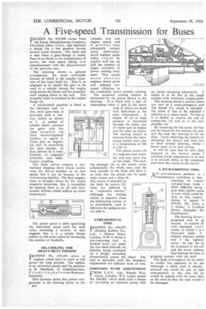
PATENT No. 694,898 comes from the-Eaton Manufacturing Company, Cleveland, Ohio, U.S.A., and discloses a design for a bus gearbox having several novel features. The chief one is that when a gear-change is made, there is no break in the transmission of power, the next speed taking over simultaneously with the disconnection of the previous one.
The drawing shows a general arrangement, the most noticeable feature of which is the angular situation of the input shaft (1). This is so disposed as to enable the gear to be used in a vehicle having the engine lying across the frame and the propeller shaft sloping down to the axle. The propeller shaft is attached to the output flange (2).
A two-layshift gearbox the left-hand end; in this, each gear-train is provided with a one way clutch as shown at 3. A system of tubular shafts connects the gears with the input member via three electro-magnetic clutches in region 4. These play an important part in smoothing .
the gear change, as they operate by a corn bination of magnetic attraction and eddycurrent coupling.
The latter action Imparts a preliminary slipping drive which accelerates the driven member to its new speed; this it can do because of the overrunning clutches. The final engagement is brought about by the actual magnetic attraction; this is intensified by running them in an oil and ironpowder mixture which stiffens up when magnetized. is fitted at
The patent gives a table specifying the individual trains Wed for each ratio, including a reverse. It also suggests that it is a simple design *matter to add more ratios by increasing the number of layshafts.
OIL-COOLING FOR HEAVY-DUTY PISTONS
PATENT No. 695,294 refers to engines which have to work at full power for long periods. The subject is an oil-cooled piston and the patentee is K. Maybach, 21 Zeppelinstrasse, Friedrichshafen-am-Bodensee, Germany.
This inventor states that piston temperature is the limiting factor in the a32 cylinder size and engine speed, and if pistons were adequately cooled, many multi-cylindered engines made today could be equally well run on half the number of larger cylinders if piston cooling were used. This would mean shorter engines, fewer parts and reduced torsional vibration in the crankshaft, hence sweeter running. The proposed cooling scheme is illustrated by the piston shown in the
drawing. It is fitted with a pair of telescoping tubes (1 and 2) the lower ends of which are fitted with ball-joints at the pipe connections. A supply of oil at high pressure is circulated through the pipes, one of which acts as supply and the other as return. The cooling circuit is separate from the lubricating system and runs at a temperature of 100 to 150° C.
The piston crown (3) is a separate steel member and may carry one or two rings. The cooling passages (4) in the crown cover substantially the whole area, and the heat transfer to thc body and skirt is so little that the piston can be made truly round and a close fit.
The crown is attached to the body by screws (5); these are referred to as "expansion screws." Although the cooling circuit is separate from the lubricating system, it is, nevertheless, used to lubricate the gudgeon-pin via tube 6.
TYRE-REMOVAL TOOL DATENT No. 694,973 I (Dunlop Rubber Co., Ltd., 1 Albany Street, London, N.W.1) shows a tyre-removing tool. A hooked lever can press the tyre bead inwards, its fulcrum being anchored on a bridge extending diametrically across the wheel. The tool is provided with the necessary adjustments for different sizes of tyre.
INJECTION PUMP ADJUSTMENT L'ROM C.A.V., Ltd., Warple Way, I Acton, London, W.3, comes patent No. 694,803, which deals with a means for providing an injection pump with an initial matching adjustment. object is to do this in the sinapt manner with minimum complication.
The drawing shows a section throu one unit of a multi-plungered pun The barrel (1), which is clamped top screw 2, has to be adjusted 1 position in a rotary sense. To this er it is drilled to receive the end of tommy-bar (3) and so is the pini member (4).
By loosening the top screw, the bar can be hurled by the tommy, the pini and the rack bar moving at the sai time. _Upon removing the tommy af clamping, the pinion and rack retu to their normal position, whilst t barrel stays in its new setting.
It will be seen that he only chan required in the normal pump enabling initial adjustments to be mar is to provide holes in the componer and form the recess in the barrel.
A STUD-GRIPPING TOOL
AN ever-recurrent problem in t 1-1, maintenance workshop is that inserting or removi cylinder-head studs, t chief difficulty ,being grip them tightly enoul A tool which could be help in this respect shown in patent l■ 695,021 (W. Jones a J. Green, 12 Lottbrid Down, Hampden Pai Eastbourne).
The drawing shows t proposed tool in pl section. It consists of well-designed coll. chuck, in which 1 is t three-jaw collet, 2 tubular distance memb and 3 the tighteni. screw. In use, the sti (4) is placed in the col] and the screw tightent thus forcing the jaws in gripping contact with the stud.
The body is hexagonal on its outsic to enable two spanners to be use Although a plain stud is shown, screwed one could be just as easi manipulated; .in this case the jal would be tapped with the same thre as the stud so that the stud would n be damaged.