


TRANSMITTING POW AROUND CORNERS
Page 26
Page 27
Page 28
If you've noticed an error in this article please click here to report it so we can fix it.
LIKE so many other things in our mechanized world the humble universal joint has long ago been relegated to the accepted things in life, and now that so many commercial-vehicle men are in the Forces, they will be meeting with new and rather fearsomelooking joints of a complexity for which the need may not be at once apparent. The fundamentals of these mechanisms present an interesting study, particularly as some of the post-war new models will no doubt feature independent suspension, and front-wheel and four-wheel drives, requiring the incorporation of the later universal
joint developments. • Non-metallic joints, such as the fabric disc and the Layrub type, require little explanation, and it will he obvious that they are restricted to small angular movements—no detriment when used in the propeller shafts of orthodox chassis. However, this limitation renders them unsuitable for front axles where operating angles of up to 35 degrees and sometimes even more are . required.
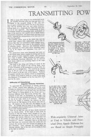
The mechanical, joints most frequently met with are of the Hooke type, which consists of driving and driven forks splined to their respective shafts, and connected by a cross or spider.. When working at small angles, this mechanism functions efficiently, but an inherent fault shows itself to an increasing degree as the angle becomes larger.
This fault is the rising and falling in speed of the driven shaft with respect to the driving shaft, twice in each revolution, in all circumstances except when the shafts are in a straight line. The variation in velocity may be 30 per cent. at an angularity of 30 degrees, and as much as 54 per cent. at 40 degrees. Variation of angular velocity on a normal vehicle is unnoticeable, for besides being small in itself as a result of the small mis-alignment, it is damped out by the long drive shaft and by the tyres. .
Difficulty of Visualizing Angular Velocity Variation To appreciate this phenomenot of 'Velocity variation may, at first, present some difficulty, but if the cross or spider be visualized as a connecting link joining a pair of opposite fork ends; it can be seen why one end loses some velocity in being guided at the driven end in a direction different from that of the driving end. The obliquity of the link, as represented by its angle with the plane of the area circumscribed by the circular path of one of its ends, alters as it revolves. Therefore, because its length is constant, the distance its other end travels for 180 degrees of the driven end, will be, .say, 190 degrees on one side and 170 degrees on the other. An analogy may be found in the engine, where the crankshaft runs at constant speed, whereas the piston moves with varying velocity.
Now let us take the case of three shafts connected by two Hooke joints. If the angle of both joints be identical it will not require much thought to see that by positioning the two joints so that they are similarly arranged, the velocity difference of the final shaft will be 'twice that of thee middle one, but if the joints be arranged in " mirror " symmetry, that is, so that ,first and last forks are horizontal when the centre two are vertical, the second joint will increase its speed as the first decreases. Thus, although the centre shaft has varying velocity, that of the last will be similar to that of the first or constant. • It requires similar angles of the two joints to provide constant velocity, and this may be satisfied in two ways —either, by making driving and driven shafts parallel or by arranging thara so that they are co-incident and the connecting shaft is perpendicular to a line bisecting the angle.
The universal joint incorporated inside a wheel hub must obviously be compact. Whilst limited rigidly in respect of size, it has to transmit high torque and at the same time to drive through any angle to which the wheel turns.
A joint frequently found on English vehicles which fulfils these requirements is the Tracta, and although of awe-inspiring appearance, it is simple in principle. The designer, in his endeavour .to minimize overall dimensions, has eliminated pin joints in favour of large forks integral with the shafts, but they are still pivots and should be imagined as such.
The reader should visualize a: driving shaft and a driven shaft each having a member pivoted to it, and the two members in turn being pivoted together, the axes of respective ,pivots being at right angles to-,each other. This will be recognized as an embodiment of what is in effect a double Hooke joint, with the con-, necting shaft reduced to Zero length.
At least one attempt has been made to produce a joint of this nature with pin-type pivots, but adequate strength and resistance to wear are practically unobtainable within the dimensional limitations.
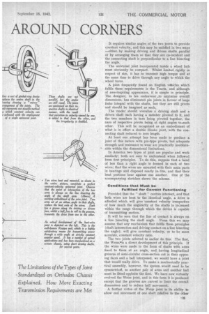
In America two types of joint are popular and work similarly; both are easy to understand when followed from first principles. To do this, suppose that a bend of less than a right angle is formed in each of two wires; that the wires are mounted with their main parts in bearings and disposed nearly inline, and that their bent portions bear against one another. One of the accompanying sketches shows the scheme.
Conditions that Must be Fulfilled for Correct Functioning
Provided that the " shaft" centres intersect, and that both wires are bent to the identical angle, a drive is afforded which will give -constant velocity irrespective of how much the angularity of the shafts is increased within the range through which the device is capable of transmitting motion.
It will be seen that the line of contact is always on a line bisecting the shaft angle. From this we may assume that any mechanism that fulfilq these principles (shaft intersection and driving contact on a-line bisecting the angle), will give constant velocity, or to be more accurate, constant velocity ratio.
The two joints referred to earlier do this. The first, the Weiss,olis a direct development of this principle. If the wires were made in the form of shafts with arms fixed to them at an angle, and having longitudinal grooves of semi-circular cross-section cut in their opposing faces and a ball interposed, we would have a joint that would really drive. To make a mechanically practical assembly, however, the system would need to be symmetrical!, so another pair of arms and another ball must be fitted oppbsite the first. We have now virtually evolved the Weiss joint, and in this form it is produced except that the grooves are curved to limit the overall dimensions and to reduce ball movement.
A further virtue of the Weis joint is its ability to allow end movement of one shaft relative to the other without detriment, thus eliminating the need for sliding splines. Anyone who has tried to move a gear lever on a vehicle, without disengaging the clutch and while load is being transmitted, will appreciate the force required to slide the normal universal joint on its splines as is necessary when the axles rise and fall.
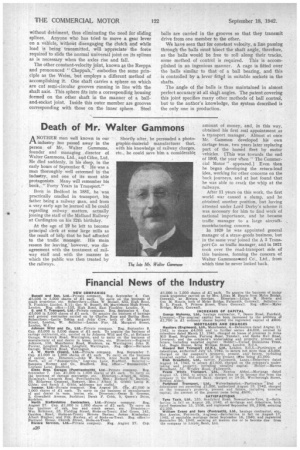
The other constant-velocity joint, known as the Rzeppa and pronounced " Cheppah," embodies the same principle as the Weiss, but employs a different method of accomplishing it. One shaft carries a sphere on which are cut semi-circular grooves running in line with the shaft axis. This sphere fits into a corresponding housing formed on the other shaft in the manner of a balland-socket joint. Inside this outer member are grooves corresponding with those on the inner sphere. Steel bills are carried in the grooves so that they transmit drive from one member to the other.
We have seen that for constant velocity, a line passing through -the balls must bisect the shaft angle, therefore, as the balls would be free to roll along their tracks, some method of control is required. This is accomplished in an ingenious manner. A. cage is fitted over the balls similar to that of a ball bearing, and this is controlled by a lever M.N.(' in suitable sockets in the shafts.
The angle of the balls is thus maintained in almost perfect accuracy at all shaft angles. The patent covering this joint specifies many other methods of ball control, but to the author's knowledge, the system described is the only one in production.