


Multi-axled Vehicle Design
Page 52
If you've noticed an error in this article please click here to report it so we can fix it.
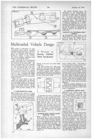
TO enable a semi-trailer to carry increased loads without exceeding the legal load-per-axle limit, is the purpose of a multi-axled design shown in patent No. 578,633, by E. Hoobler, Southwest, Canton 7, Ohio, U.S.A. The scheme employs additional axles
• having a self-steering action.
The tractor unit is of conventional design, being fitted with a turntable for the reception of the semi-trailer. The latter is provided with a rear turntable (1) about which is pivoted a sub-frame (2). On the forward end of the subframe is another turntable (3) which forms a pivot axis foi axle 4. Instead of a plain bore, however, the king-pin works in a slot. Attached to the middle axle is a drawbar member (5). which is pivotally connected to the semi-trailer frame at point When the tractor makes a turn, the middle axle swings about the drawbar pivot, its king-pin slides in the slot, and the whole bogie swings into the position shown in the upper drawing. All the wheels automatically track to a common centre, which prevents scuffing of the tyres.
A TYRE-REMOVING TOOL facilitate the removal of heavy
'TO facilitate from their rims, is the purpose
of a tool shown in patent No. 578,761, by F. Daw, and the Dunlop Rubber Co., Ltd., I, Albany Street, London, N.W.1. The aim of the scheme is to prevent damage to the cover even when ightly rusted on.
The outfit consists of a table upon which the tyre and wheel are placed, studs being provided to prevent turning. A central screwed pillar carries a rotating head fitted with two wheels at its extremities; the drawing shows details of one of the wheel heads.
In operation the head is rotated, and descends as it turns, bringing the wheels (I) to bear on the bead (2) of the tyre. At the same time, the wheel bearing pivots about the pin 3 and is thereby urged inwards under the rim. An adjustable stop (4) limits this inward movement and eventually compels the wheels to move in a vertical direction
only. The beads can thus be forced away from the rims by a harmless rolling motion.
DUMPER WITH ARTICULATED DRIVING UNIT
THE principle of unit construction, including engine, gearbox and back axle, is often used in dumper vehicles, but has the disadvantage that it does not permit a sprung axle to be used. To achieve this is the object of an improved dumper shown in patent No. 578,565, by E. Boydell and Co., Ltd., and J. Coldwell, both of Elsinore Road, Manchester, 16.
The scheme disclosed retains the advantages of unit construction by allowing the engine and the gearboxcoin-axle to pivot about a mid-point
(1). An interior joint deals with the• drive, whilst the casings are united by
a spherical joint. The axle can be mounted on springs (2) and the engine is resiliently, suspended on a rubbermounted cross-bearer (3) at the end. No mention is made of a second mounting for the engine, so presumably its weight is taken by the springs of the axle-casing.
NOVELTY IN UNIVERSAL-JOINT DESIGN
AUNIVERSAL joint, based on the principles of involute gear teeth, is shown in patent No. 578,287, by N. Straussler, Byron House, St. James's
Street, London, S.W.I. The design is of the type giving constant angular velocity throughout its working angle.
The drawing illustrates the elements of the joint, which can be regarded as a pair of wide-angled bevel gears. All the working surfaces are of conical outline, the apex being located in the centre of the joint. Here, as shown, a steel ball may be located tn act as a centralizing member. The teeth are of greater depth than standard, so as to prevent bottoming when the shafts are at maximum deflection.
Although intended originally for the propeller drive of military landing craft, the scheme obviously has a much wider scope of application.
A COMPOSITE PISTON RING
PATENT No. 578,733 comes from Hare! Mechanical Processes, Ltd., 33-37, Regent Street, London, W.1, and discloses an improved type of piston ring. The aim of the design is to give an engine a longer life by reducing the tendency to wear the cylinder and rings out of round.
The construction embodies a T-secLion ring (1) of aluminium alloy; this is unsplit and closely fits a deep groove (2) in the piston. A plain unsplit lower ring (3), also of aluminium alloy, converts the T section into a U shape, and forms the housing for a pair of rings of
the normal pattern, The rings are, however, recessed at the hack to receive thin steel springs (4) between them, as a means for urging them into close contact with their housing. In addition, radially acting spring rings (not shown) are employed to maintain firm contact with the cylinder wall.