


RELATING TO THE BACKING OF TRAILERS.
Page 70
If you've noticed an error in this article please click here to report it so we can fix it.
A Résumé of Recently Published Patent Specifications.
ALL those who have had experience in the use of .trailers will be well aware of the difficulties that arise when such Vehicles are taken into places -where backing out is needed, which is often the case where goods have to be delivered to factories. Realizing the existence of this difficulty we are somewhat surprised that makers of this class of vehicle have not given more attention to the introduction of some device which will simplify the task of the driver.
The specification of H. Hillcoat, No. 277,176, describes a form of trailer which, it is claimed, reduces this trouble.
The inventor points out that, with an ordinary trailer, should the front wheels be at an angle with the body the latter tends to swing round when the tractor moves in a backward direction. This is well known to anyone who has attempted to back with a trailer. In the present invention the front axle is rigidly locked and is not affected by the steering of the tractor. The rear wheels are pivoted in the centre of their axle and are connected by cross-rods to the cross-beam mounted rigidly with the pullbar, which is mounted on, the pivot shown.
By this means, when the tractor turns to the right when travelling in a forward direc4ion, and thus describes part of a circle in a clockwise direction, the draw-bar swings in a clockwise direction on its pivot, carrying with it its cross-bar, and causing the rear axle to swing in an anticlockwise direction, with the result that the trailer follows the tractor by describing a circle in a clockwise direction.
We presume that the, inventor has given due consideration to the fact that such an arrangement, although it appears to he excellent when considered from a reversing point of view, may cause trouble due to the trailer swinging outwards from the track of the tractor.
Brake Compensating and Adjusting. THE simultaneous adjusting and compensating of brakes, both front and rear, is the object of the arrangement described in the specification, No. 277,059, in the names of Sydney Smith and A.C. Cars, Ltd. A cross shaft, in the form of a tube, is carried right across the frame and is borne in two hearers, one on each side member. Attached to this tube is a lever that may be actuated
either by hand or foot, as shown in the upper view, at the right band of the illustration we publish. Attached to each end of the tube is a carrier of the pins which hold the pulleys shown, over' which the cables operating the brakes pass, one end leading to the front brakes and the other to the rear brakes.
: Near the ends of the tube rollers are mounted in forked members, these being arranged so that they can slide within 'the tube, but placed so that they must revolve with the • c48 tube. Each cable passes over one of the rollers outside the tube, then up the tube and over a roller within the tube and again over a roller outside the Aube, its ends passing to one or other of the brakes. It is obvious that this arrangement affords a complete balance for . each pair of brakes, so far as that side is concerned, but there is still a further balance action contained in the device, as the ends of the forked members are screwed, tight and left, and their distance apart can he adjusted by. means of the sleeve which is internally screwed to receive them. By this means a perfect adjustment and a perfect balance are obtained at the same time.
The sleeve is provided with external splines and passes through a short sleeve, which is internally splined to engage the long sleeve, and carries a worm wheel on its outer surface. This worm wheel is operated by means of a worm and small hand wheel, which is placed in a convenient position for the driver to operate while driving. By this means a perfect balance between all four brakes and an instantaneous adjustment are obtained.
The worm and wheel are very similar to the arrangement used for many years for the adjustment of the Cominer brake.
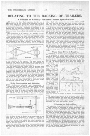
Where Great Power is Required.
A METHOD of obtaining great power for such operations as propelling a tractor under difficult circumstances, driving a winch for lifting heavy articles, or for driving
a digger, etc., where greater power is required than that 'provided by the lowest gear, is described in the specification of Spencer (MeIksham), Ltd., and John Philip, No 277,174. It should prove to be a cheap and simple way of obtaining a very slow movement and increased power.
The l'Thvice consists of a silaft, driven by the engine, which is pro. aided with an eccentric actuating a pawl which engages in a ratchet wheel end thus provides a step-bystep movement of either the road wheels or a winch, or any appliance where great power is required. A second pawl, or detent, is arcivided to prevent the ratchet wheel from moving backwards and following the pawl on its idle stroke. A lever and chains arc shown as means for disengaging the pawls. The type of pawl shown is by no Means a good form, as movement between its point and the tooth it; engages is taking plaee' during the heavy load of the active stroke. Two eccentrics, each with a. pawl, would give a more even movement and would not require a detent.
Of Interest to Bodybuilders.
AN apparatus for grinding certain parts of the bodies of motor vehicles is described in patent specification No. 277,20;3, by Joseph T. Strattnan, of Detroit, 'U.S.A. The particular use for which the device seems to have been designed is the trimming of door and window frames which are made or covered with sheet metal. Where such metal parts meet they usually require some hand filing and emery papering, and it is to provide a quicker means for performing these operations that the device has been designed. There is little doubt that there are many other operations in body making where such a tool would be found of use.
The tool consists of a flexible shaft counected to a spindle which is provided with a handle at both ends of the cone. carrying the grinding wheel or, abrasive paper cone. By means of the two hand grips the operator has better control of the grinding cone. The cone is described as being, in some cases, made of rubber.