


The New 28h.p. Milnes-Daimler Chassis.
Page 4
Page 5
Page 6
If you've noticed an error in this article please click here to report it so we can fix it.
Exclusive Particulars.
Much interest will attach to this, the first published account of the 1907 type motor omnibus chassis which is now being put through in large numbers at the huge works, at Marienfelde, near Berlin : Milnes-Daimler, Limited, may be justly proud of the fact that it has more self-propelled passenger vehicles, on the roads of London, than any other maker. Our fortnightly census of the numbers of various types of motorbuses doing service in the Metropolis, one of which appears in this issue, shows that nearly one-third of the total number of the motorbuses which were " in coinmission" on Monday afternoon last bore the familiar name of Milnes-Daitnler, Limited. This large percentage is the
result of a determination on the part of Mr. H. G. Burford, the managing director, to bring the design of this chassis to as near perfection as possible. Our issue of September 20th last included a descriptive article of the company's distributing deptit in London, where all chassis undergo a final examination at the hands of highly-qualified mechanics, before they are handed over to their respective purchasers.
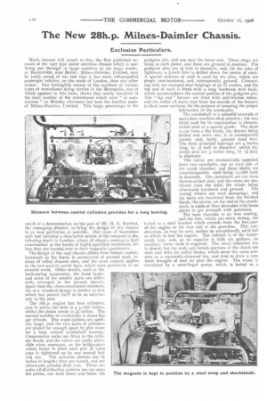
The 28h.p. engine has four cylinders. cast in pairs; the bore is 4 5-16th inches, whilst the piston stroke is 5.& inches. The normal number of revolutions is about 850 per minute. The water-jackets are specially large, and the two pairs of cylinders are placed far enough apart to give room for a long central crankshaft hearing. Compression cocks are fitted to the cylinder heads, and the valves are easily accessible when necessary, as the bridge-piece which keeps in place each pair of valve caps is tightened.up by one central bolt and nut. The cast-iron pistons are 61 inches in length ; they are turned, and are afterwards ground dead true. Three annular oil-distributing grooves are cut upol the piston, one each above and below the gudgeon pin, and one near the lower end. Three rings are fitted to each piston, and these are ground in position. The gudgeon pins are if inch in diameter, and, for the sake of lightness, a t-inch hole is drilled down the centre of each. A special mixture of steel is used for the pins, which are deeply case-hardened, and, subsequently, ground. Connecting rods are stamped steel forgings of an II section, and the top end of each is fitted with a long hardened steel bush, which accommodates the central portion of the gudgeon pin. The "big end" brasses are lined with anti-friction metal, and six radial oil ducts lead from the outside of the brasses to their inner surfaces, for the purpose of ensuring the proper lubrication of the crank-pins.
The crankshaft is a splendid example of up-to-dale machine-shop practice; the material used for its construction is chromenickel steel of a special grade. The shaft is cut from a flat blank, the throws being drilled and sawn out; it is. subsequently turned, and, lastly, ground dead true. The three principal bearings are 4 inches long, by if inch in diameter, whilst the crank pins are 3 inches long, by ti inch in diameter.
The valves are mechanically operated from two camshafts, one. on each side of the crank chamber, and these shafts are interchangeable,, each being 13-16th inch in diameter. The camshafts are cut troin chrome-nickel steel, and the cams are machined from the solid, the whole being afterwards hardened and ground. The timing wheels are steel stampings, and the teeth are machined from the finished blank; the pinion, on the end of the crankshaft, is made of fibre shrouded with brass plates to get strength with quietness. The base chamber is an iron casting, and the feet, which are extra strong, are bolted to a steel bracket which extends from the fore-part of the engine to the rear end of the gear-box. This construction, as may be seen, makes an exceptionally solid bed to which to bolt the engine. The radiator is of the honeycomb type, and, as its capacity is fully six gallons, no auxiliary water tank is required, The usual induction fan is abserit, but the male and female portions of the clutch are each cast with six radial blades, which serve the same purpose as a separately-mounted fan, and tend to draw a constant draught of cool air past the engine. The water is circulated by a centrifugal pump, which is bolted to a bracket on the engine, and is gear-driven from the fore-end of the right-hand (ex haust) camshaft. When the engine is running normally, the pump spindle revolves at about 1,420 revolutions per minute, and, at this speed, it passes over 17 gallons of water in a minute, which means that the maximum contents of the radiator, Pipes, and water jackets, are circulated nearly three times in each minute.
The ignition is by a Simms-Bosch magneto; this is bolted to the engine, near the dash, and its armature is driven, by gear, from the tail end of the exhaust camshaft. The magneto is placed in a very accessible position, and it is held down upon its bracket by a steel bridle strap and a shackle bolt. The plugs are similar in design to those which have always been used on this make of chassis, and soapstone insulators are, as before, employed for the plug pills. The main bearings of the crankshaft, and its pins, are lubricated by a small force pump, which is carried upon a bracket at the rearward end of the base chamber; the reciprocating ram is actuated by a crank on the Lail end of the inlet camshaft, and this gives a piston stroke of about inch. Three pipes branch from the pump: one to the central bearing of the crankshaft, and one to each of the end bearings. The crankshaft is, in reality, hollow throughout, but the bore is plugged in two places, thus dividing it into three separate portions. The first portion includes the front journal and pin; the second, the central bearing and the two adjacent pins; and the third part, the rear journal and pin. The lubricating oil passes from the pump, along the three pipes, to the bearings, and a portion of it finds a way into
the central bores by means of oil ducts, which are drilled from the surface of each journal to its interior : similar ducts, in the centres of the pins, ensure a constant flow of oil to the "big ends." The surplus oil from the various bearings falls to the bottom of the base chamber, and runs into an oil-pot, fitted with a wire-gauze strainer : the oil runs, by gravity, to the reservoir, which is a cylindrical tank, carried near the engine, and a pipe connects this with the pump, so that a constant circulation of the oil is effected. An indicator, placed upon the dash, shows the driver the amount of oil pressure, and, should the pump fail at any Lime, his attention would at once be drawn to the fact.
Transmission is, primarily, by a leather-covered clutch; the female portion of this is 20 inches in diameter, and has a face 2 inches wide. The male member is withdrawn by a bridge piece, whiCh carries, at its centre, a thrust block, whilst the two ends are furnished, respectively, with a powerful spring, and a steel rod with a long sleeve nut for the necessary adjustment : the end of the bridge-piece carrying the spring is connected to the foot pedal. The clutch shaft is attached to the first shaft in the gear-box by flanges, and this first gear-box shaft carries the sliding gear wheels, which are bolted to sleeves having six internal feathers; corresponding key-ways are cut in the shaft. The sliding gears arc controlled by a lever, working in a gate, and this actuates one of three selector rods. The secondary shaft is situated beneath the first-motion shaft, and its gear wheels are bolted to flanges, which are integral with the shaft. The forward gear ratios are : 2, , Si-, and 12 miles per hour, and the reverse is 2;miles per hour; these speeds
are calculated with the engine running normally. The gears are cut from a special grade of chrome-nickel steel, and are practically indestructible. A cardan shaft, II inch in diameter, transmits the power from the gear box to the differential gear. Both ends of the shaft are furnished with universal joints; the joint for the fore-end is of the usual pin and jaw type of the ordinary pattern, whilst the rear extremity is provided with one of a special design. A toothed pinion is bolted to the shaft, and this is an easy fit in an internally-toothed box, forming the front-end of the short shaft which drives the differential gear ; the pinion has teeth of a special form, to allow of either horizontal or vertical movement. The differential shaft drives the back wheels by pinions, which mesh with internally-toothed riros upon the inner side of the driving wheels; this form of drive has been the standard on the Milnes-Daimler vehicles since the gold medal, for its class, was obtained in the Liverpool Trials of 1901.
The brakes are a special feature in this chassis, and three are fitted, so that very ample braking power is obtained. The first (foot pedal) acts upon a drum xi inches in diameter, by 21 inches wide, bolted to the forward end of the secondary shaft in the gear box; the second, also operated by a pedal, has two drums, one at each end of the differentia; ,haft, and both are the •same size, viz., toi inches by zt inches. The drums for the above brakes are water-cooled; the water supply is controlled by two taps on the dash. Thq third brake is new, and takes the form of two blocks, 12 inches in length, which have V-shaped working faces running in a groove of similar section on the inner edges of the back-wheel rims.
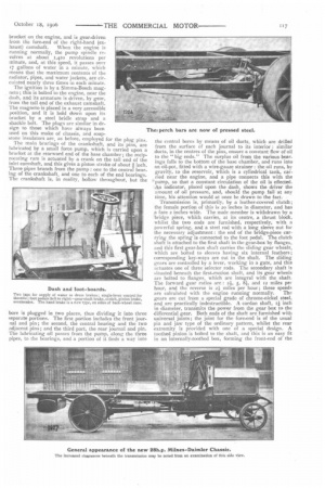
The frame is now constructed of pressed steel; the maximum depth of the section is 6 inches, and, as will be seen in the illustration, the side members taper slightly towards the ends. The five cross stays are also of pressed steel, and one of these is in the form of a deep girder, and carries the front end of the two pressed-steel perch bars; these are now, instead of being nearly parallel with the side members, brought within r5 inches of each other at their forward
ends. The gussets, holding the transverse stays to the side members, are extra strong, and all rivets are driven in hot. The principal dimensions are : Frame, 19 feet it inches long; wheel base, 13 feet; wheel track, 5 feet 6 inches; height of frame, unloaded, from ground, 2 feet io inches; width over axle caps, 6 feet 64 inches. The back axle is a heavy forging of H section, and the journals are 81 inches long by 3 inches in diameter, whilst this axle, instead of being cranked as heretofore, is now straight. The front axle is, also, nearly straight; it has an H section, and the journals are 6:1 inches by zi inches.
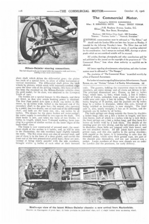
The back springs are slung outside the frame by shackles 4 inches long; they are 4 feet 2 inches in length, and have nine leaves, each of which is 3 inches wide by inch thick; the front springs are 3 feet 4 inches long, and they have five leaves 21 inches wide by ft inch thick. The details of the steering gear are very strong, and the ball joints are i inch in diameter; these balls are integral with their levers, and are not attached thereto. All the joints have screw-down grease cups, and this also applies to the spring shackles ; with regard to the latter, it is interesting to note that the threaded necks, which carry their grease cups, are part of the shackle pins themselves, and are not screwed into a socket. Large numbers of these new chassis are on order for London and the provinces, for early delivery.