


Patents Completed.
Page 32
If you've noticed an error in this article please click here to report it so we can fix it.
STEAM GENERATOR.—Mitchell.— No. 27,067, dated December 28th, 1905— The coils (13) of the generator are disposed in spiral form around a horizontal burner (C). Fuel is admitted by a conduit (M), and traverses round a rod (Q), having collars (q). Each collar is pierced to allow the passage of the fuel, but the orifice in one collar does not align with the other. The fuel passes from this conduit to the nozzle (R), and escapes thence
into the mixing chamber (D). One end of this is open to the atmosphere, so that atmospheric air is drawn in with the fuel, and the other end opens into the main chamber of the burner (C). This burner is perforated on its lower side, but not immediately over the conduit (M). The result of this arrangement is that the jets from the orifices radiate obliquely from the burner, so that the gases of combustion thoroughly circulate amongst the tubes, whilst the conduit (M) receives sufficient heat to vaporise the fuel as it traverses the same. The coils (B) are enclosed by a casing (A), and the burnt gases finally make their escape by an exhaust conduit (E) at the bottom of the casing.
FORGE.—Rasnick.—No. 19,564, dated September 27th, 1905.—In order that the fuel may he evenly and readily fed to the forge, the tubular body (10) of the latter has a movable bottom 03), The blast. tube (25) is arranged in the centre of the body (10), and extends through the movable bottom. The bottom has secured to it a rack 115) operated by a pinion (17), and this is rotated by a hand-wheel (21). When the bottom is at the lowest position, the fuel is packed in, and as it is consumed the bottom is raised so that the fuel is fed evenly up to the top of the blast-tube. The blast is controlled by a valve (261 carried by a stem (27) provided with an arm (28).. This arm lies on a sloping guide (30), so that, by moving it in one direction or the other, the valve (26) may be raised or lowered to decrease or increase the blast.
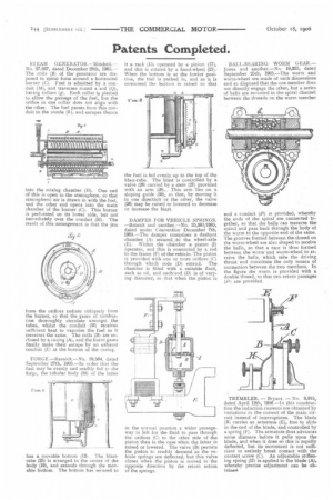
DAMPER FOR VEHICLE SPRINGS. —Batault and another.—No. 25,381/1905, dated under Convention December 7th, 1904.—The damper comprises a dashpot chamber (A) secured to the wheel-axle (E). Within the chamber a piston (I) operates, and this is connected by a rod to the frame (F) of the vehicle. The piston is provided with one or more orifices (C) through which rods (D) extend. The chamber is filled with a suitable fluid, such as oil, and each rod (D) is of varying diameter, so that when the piston is
in the normal position a wider passageway is left for the fluid to pass through the orifices (C) to the other side of the piston than is the case when the latter is raised or lowered. The valve (B) permits the piston to readily descend as the vehicle springs are deflected, but this valve closes when the piston is moved in the opposite direction by the return action of the springs.
BALL-BEARING WORM GEAR.— Jones and another.—No. 19,325, dated September 25th, I905.—The worm and worm-wheel are made of such dimensions and so disposed that the one member does not directly engage the other, but a series. of balls are mounted in the spiral channel between the threads on the worm member and a conduit (di.) is provided, whereby the ends of the spiral are connected together, so that the balls can traverse the spiral and pass back through the body of the worm to the opposite end, of the same. The grooves formed between the thread on the worm-wheel are also shaped to receive the balls, so that a race is thus formed between the worm and worm-wheel to receive the balls, which take the driving thrust and constitute the only means of connection between the two members. In the figure the worm is provided with a double thread, so that two return passages. (di) are provided.
TREMBLER. — Bryant. — No. 8,915, dated April 12th, 1906 —In this construction the induction currents are obtained by variations in the current of the main circult instead of interruptions. The blade (R) carries an armature (E), free to slide in the end of the blade, and controlled by a spring (19. The armature thus advancessome distance before it pulls upon the blade, and when it does so this is rapidly deflected, but its movement is not sufficient to entirely break contact with the contact screw (C). An adjustable stiffening spring (H) is applied to the blade (A), whereby precise adjustment can be obtained