


Patents Completed.
Page 20
If you've noticed an error in this article please click here to report it so we can fix it.
Complete specifications of the following patents will be sant to any address in the United Kingdom upon receipt of eightpence per copy at the Sale Branch, Patent Office, Holborn, W.C.
MICROMETER GAUGE. — Elphinstone.—No. 25,529, dated 26th November, 1908.—According to this invention, a micrometer gauge is fitted with a handle by means of which the latter may be held by two fingers, leaving the first finger and the thumb to operate the screw. The handle is clamped on to the C-shaped member of the micrometer gauge and is secured by means of a screw and block.
DETACHABLE WHEELS.—Pugh.— No. 22868, dated 27th October, 1908.— This invention relates to detachable wheels of the type described in specification No. 9,033/1909, in which the hub of the detachable wheel is adapted to fit over a permanent hnli and is held thereon by locking means. The object of the present invention is to provide a detachable wheel with simple means whereby the outer end of the detachable hub, as well as the inner end thereof, may be directly supported, so that a considerable clearance may he allowed between the inner surface of the detachable hub and the outer surface of the permanent hub. The detachable hub is provided with a tapered face at its miter end by turning or bending over the edge thereof, and a lockrng nut is provided which has a similarly-tapered face that abuts against the tapered end of the detachable hub. The inner end of the permanent hub is formed with a conical surface, and the inner end of the detachable hub is similarly shaped. It will be seen that, on screwing home the locking nut, the detachable hub will be supported by its two coned or tapered faces; if desired, a considerable clearance may be allowed between the permanent hub and the detachable hill,. DUAL IGNITION.—Bell.—No. 195, dated 4th January, 1909.—This invention relates Le a system of ignition in which an induction coil is employed in conjunction with a high-tension magneto. According to the present invention, a hightension two-way switch is mounted on the magneto, and operates either to cut out the induction coil or the magneto from the distributor arm, so that the two circuits are distinctly separated. This switch is actuated by means of a Bowden wire, the operating button of which may he situated at any convenient part of the vehicle, for instance on the dashboard. Attached to the magnets of the magneto is an insulating block in which is formed a socket to receive a highly-insulated cover for a Bowdon wire. This Be wden wire or conductor is
in electrical connection with the hightension wire of the induction coil, and is also connected to a button mounted on he dashboard. This button may conveniently be carried by a plunger or pear switch which controls the battery circuit. The Bowden wire is adapted to he projected by means of the button through the insulated block carried by the magnets of the magneto, so as to contact with a blade that is in electrical connection with the distributor. This blade normally contacts with a conductor that is in electrical connection with the magneto high-tension circuit, but, on the Bowden wire being forced into contact with this blade, the high-tension circuit of the magneto is broken. Thus, it will be seen that the engine may be started " on the switch " and also ignition ensured during slow running.
BALL BEARINGS. — Deutsche Waffen-und Munitinnsfahriken. — No. ball bearings, the outer-race ring of which has a spherical surface which fits an outer casing having a correspondingly-spherical, internal surface, so as to allow the bearing to move nr to adjust itself to the shaft. According to the present invention, the enter casing is in the form of an endless ring, and the bearing is pressed into this ring at an angle of 90 degrees to the latter, the elasticity of the metal allowing the bearing to enter.
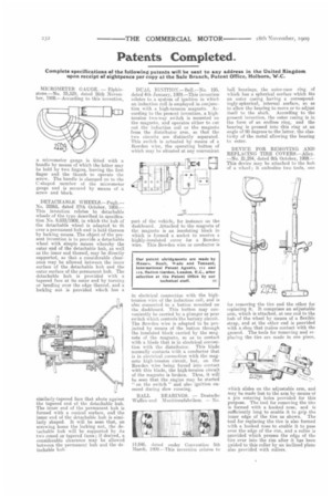
DEVICE FOR REMOVING AND REPLACING TIRE COVERS.—Alley. —No. 21,294, dated 8th October, 1908.— This device may be attached to the huh of a wheel; it embodies two tools, one
fur removing the tire and the other for replacing it. It comprises an adjustable arm, which is attached, at one end to the hub of the wheel by means of a flexible strap, and at the other end is provided with a shoe that makes contact with the ground. The tools for removing and replacing the tire are made in one piece,
which slides on the adjustable arm, and may be made fast to the arm by means of a pin entering holes provided for this purpose. The tool for removing the tire is formed with a hooked nose, and is sufficiently long to enable it to grip the inner edge of the tire as shown. The tool for replacing the tire is also formed with a hooked nose to enable it to pass over the edge of the rim, and a roller is provided which presses the edge of the tire over into the rim after it hp been guided to this roller by an inclined plane also provided with rollers.