


Sectionized Body
Page 54
If you've noticed an error in this article please click here to report it so we can fix it.
ADESIGN of passenger-vehicle body that is eminently suitable for pressed-steel construction (although the possibility of using moulded plastics is mentioned) is described in patent No. 405,430 by the Pressed Steel Co. of Great Britain, Ltd., Cowley, Oxfordshire, and W. Swallow, 31, Forest Road, Headington, Oxford.
The object of the design is to produce a light, strong body having the advantage that any section can be easily replaced without disturbing the trimming or the adjacent section.
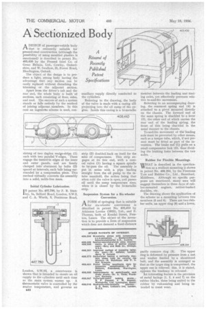
Apart from the driver's cab and the rear end, the whole body is built of sections, each consisting of floor, sides, and roof. The success of such a system stands or falls entirely by the method of joining adjacent members. In this case an ingenious scheme is used, con sistmg of two duplex wedge-strips (I) each with two parallel V-edges. These engage the turned-in edges of the inner and outer panels, and are firmly clamped into abutment by bolts (2) spaced at intervals, each bolt being surrounded by a compression piece. This method virtually converts the assembly into a solid, rattle-free mass.
Initial Cylinder Lubrication.
TN patent No. 407,790, by F. R. Stanley, la, Salford Road, London, S.W.2, and C. A. Worth, 8, Penistone Road, London, S.W.16, a contrivance is shown that is intended to ensure an oil supply to the cylinders until such time as the main system warms up. A thermostatic valve is controlled by the engine temperature, and governs an 544 auxiliary supply directly connected to the cylinders.
Referring to the drawing, the body of the valve is made with a casing (3) projecting into the oil sump of the engine. Inside this casing is a hi-metallic
strip (2) doubled.back on itself for the sake of compactness. This strip engages at its free end, with a conical valve (1) having a square spindle to by-pass the oil. The assembly is put in series with a pipe leading straight from the oil pump to the intake manifold, the action being that when cold the valve is open, and passes oil until the sump temperature rises, when it is closed by the bi-metallic strip.
Suspension System for a Six-wheeler Conversion.
AFORM of springing that is suitable for six-wheeler conversions is described in patent No. 408,410 by Atkinson Lorries (1933), Ltd., and F. Thomas, both of Hendal Street, Preston, Lancs. The object of the invention is to provide a form of suspension which does not demand a fixed-distance
member between the leading and trailing axles, yet effectively prevents relative to-and-fro movement.
Referring to an accompanying drawing, the rearmost spring end .(4) is attached to a pivot mounted directly on the chassis. The forward end of the same spring is shackled to a• lever (3), the other end of which carries the rear end of the leading spring, the front of this being shackled in the usual manner to the chassis.
To-and-fro movement of the leading axle must be prevented by other means, such as a torque tube, which, if not present must be fitted as part of the invention. The brake rod" (1) pulls on a small compensator link (2), thus-dividing the braking force between the two axles.
Rubber for Flexible Mountings.
WHAT is described in the speeificaW tion as a resilient mounting is shown in patent No. 406,204, by the Firestone Tyre and Rubber Co., Ltd., Brentford, Middlesex. Although no .specific purposes are mentioned, many uses will suggest themselves in these days of rubber-mounted engines, rubber-bushed shackles, etc.
The drawing shows the application of the scheme as a mounting between two members (5 and 6). There are two-Tubber units, an upper ring (8) and a lower, partly concave ring (3). The upper ring is deformed by pressure from a nut and washer limited by a shouldered bolt, and the assembly is arranged so that as the larger ring is compressed, the upper one is relieved; this, it is stated, opposes the tendency to rebound.
An interesting feature is the provision of metal facings (1, 2, 4 and 7) on the rubber blocks, these being united to the rubber by vulcanizing and being intended to resist wear.