


HINT'S FOR STEAM-WAGON OPERATORS.
Page 25
If you've noticed an error in this article please click here to report it so we can fix it.
Advice Given by Our Driver and Mechanic Readers.
A CCORDING to " G.P.H.," of Dept..ti_ford,,„ a number of steam wagons is in operation with the speed governor out of action, disc, in his opinion, to ignorance of the working principles of such governors and the methods of keeping them in action with good effect when speed control is required under varying steam pressures and loads. .
So far as the Pickering type of centrifugal governor, to which " refers, is concerned, the two valves controlling the steam on its way from the boiler to the engine are almost equally balanced. by the pressure of steam against ths bottom of the top valve and the top of the bottom valve, hence it wilt be seen that there is very little strain on the valve spindle. This spindle connects the 'tW-o valves arid passes upwards through the gland of the stuffing-box through the hollow axis pillar to the top of the governor, its tipper end being thref.-ded to receive two ruts, which can be run up or down and locked when the right position has been found to give the desired engine speed.
At the top of the governor is a domecover nut, which passes over the end of the valve spindle and screws down • tightly on to the upper rine' of the assembly. The valve spindle does not revolve with the balls and the -dome
CO Ver.
As the balls are rotated, centrifugal force cues them to fly outwards, pulling down the upper ring of the assembly and, of course, the dome nut, which causes downward pressure to be exerted on the nuts at the top of the valve spindle, thus closing the steam valve and cutting out the canine. The valve spindle is moved downwards against the pressure of a resistance spring working through a lever ; regulation of this spring is effected by is thumbscrew, which should only be adjusted sufficiently to lift the weight of the valves and spindle SO that the regulating nuts press lightly against the inside of the dome-covered nut when the governors are in the neutral position. Oil shouldbe applied regularly to the hole in the top of the dome cover.
-Undue importance should not be attached, says " G.P.H.," to the speed marked on the governor, as so much depends upon the spring arms carrying the balls. It can be imagined that a weak set of springs allows the balls.to fly outwards to the full extent at too• low a rate of speed, thus cutting off the , steam before the operator desires it. An importent point is the size of the driven pulley, which operates the governors' by means of bevels. When the pulley is too small, naturally the governor speed is high and steam is cut off too soon.. In such circumstances a simple method of increasing the diameter, so as to reduce the speed, is completely to en• circle the pulley with strips of belting fastened by means of quarter-inch screws with countersunk heads. One, two, or even three layers of belting may be used, each one fixed to the one below it.
When the governors are working correctly the little valve spindle should he • continually dancing up and down. and . should be quite free to work in the
gland of the stuffing-box. A mainte nance point is that the valves should be taken out and cleaned from time to time, care being taken to avoid bending the spindle.
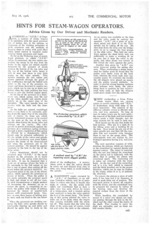
A. MA.KESHIFT repair executed by . of Dewsbury, to an oldtype Yorkshire vehicle, may be of assistance to-others who have to handle this make of vehicle. On the model with which our Contributor had to deal, a slide valve was used, driven by means of. 'a bridge-piece, and a 'tensiod spring was employed to keep the valve against the faee of the steam chest. The breaking of this spring allowed the valve to mane out of its guide when the wagon wasrunning downhill with the steam cut Off. This -meant that the valve was. clear of the ports and; of cotirSe,:doidd not seal either the inlet or the exhaust. As no spring was available at the time and the valve could be entirely dismantled, " A.W." cut a piece of 11F-in. sheet metal and fixed it to the valve spindle top by taking off the nut. He then bent down the strip over the bridge, piece so as to engage the four prongs on the slide valve. This held the valve down against the chest fairly well, not sufficiently to make a working fit on its own, but it kept the valve in the guide, and when steam was turned on this forced the valve against the ports.
Another idea given by " A.W." concerns worn-out guides for spring slippers. When overhauling a steam wagon used for timber work he found that the guides were badly worn at the back ends, whereas the front ends were reasonably sound. To overcome the trouble the old slippers were planed up square and the guides treated similarly. In order to provide strong bearing surfaces false bottoms were made, the plates being fired in position by two countersunk bolts each, so that the slippers could move easily over the surfaces.
WIIN overhauling a 5-ton Foden steam wagon there are various points to receive attention, and "H.B.," of Rotherham, deals with some of the more important. The removal of the different cylinder covers is effected with fin. and t-in. spanners. So long as care be taken joints can be used again ; the removal of the highand low-pressure valves needs a little thought, and the same process can be used in each case.
First knockout the pin that holds the link motion-. This pin is a tight fit in the lifting arms and a working fit on the link. Next knock the pin out of the valve spindle jaw and then lift the complete link and eccentric rods, bringing them to rest on the gauge plate. The valve-spindle nuts are undone by two S-shaped spanners having t-in. and "in. ends.
The next operation consists of withdrawing the pistons, which are fastened to the cross-head by tapered shanks and tapered cotters. The cotter is removed, then the nut just behind the cross-head on the piston rod is tightened, with the effect that it pushes the piston and cross-head apart. The connecting rod is taken out complete with the crosshead. At the jaw end of the connecting rod is a -Fin. bolt, which is removed and the block knocked out in the proper direction, which can be seen by looking at the stamp, either R or L, to indicate the direction.
To remove the pistons a piece of mild steel, 2 ins. long and 1 in. diameter, is used to push them out of position. The two-speed pinion is drawn off complete with the lever's, and the crankshaft may be prepared for removal by taking off the bearing caps . and drawing the tapered wedges from the front of the bearings. .
When handling the crankshaft by means of a crane two chains are used, one passing through the hole in the flywheel and the other round the centre of the shaft. Two trestles to carry the shaft are advise-131e; and on these are laid woodenbibeles.