


THE SAUNDERSON TRACTOR POWER UNIT.
Page 32
If you've noticed an error in this article please click here to report it so we can fix it.
A Résumé of Recently Published Patents.
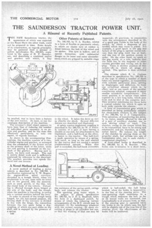
TtIE NEW Saunderson tractor, the appearance of which was expected at the Royal Show the other week, could not be prepared in time. Some details of its construction, as regards principles, may be gathered from a' perusal of patent specification No. 180;814, registered in the name of H. P. Saunderson, and descrithig a combined engine and gearbox unit which, it may
be recalled, was to have been a feature of the new tractor. At least, so ran the catalogue description of the machine.
The inventor's llief object appears to have been that of fedueing the number of individual parts necessary in an engine and gearbox, and he has done this effectively particularly, to note one aspect, as regards bearings.
As shown in the accompanying Mastro:lions, the machine consists of a twocylinder engine and gearbox, so arranged that the crankshaft of the former serves as the primary shaft of the latter, while the cam gearing is mounted on the lay shaft of the gearbox. Having said so much, we have said enough. The rest is merely detail work and as sufficiently explained by reference to the drawings. The gearbox provides twospeeds forward and one reverse.
A Novel Method of Loading.
A novel method of loading a motor , vehicle is described in No. 180,794, a specification registered by T. W. Rogers. An engine-driven spiral conveyor, shrouded in a trough which, when the mechanism is in use, rests with its lower end on the ground, lifts the material, such as sand,' gravel, or the like, into the closed body of the vehicle. Unloading is effected through doors hinged at the side of the body, and the trough, when the machine is travelling, is swung into a vertical position behind the lorry. In order to permit of the trough being hinged, for the last-named purpose, the driving shaft of the conveyor is divided in line with the binge, the connection between the two parts being a dogcoupling, of which one part slides on the shaft and is engaged by the pressure of a spring.
c48
Other Patents of Interest.
No. 180,102, by T. L. Boyden, relates to a form of flexible or pneumatic wheel, in which an elastic tyre of rubber is fitted between the hub of the wheel and its spokes. The tyre is hollow, and of special formation, with substantial flanges on its inner and outer circumferences,which are gripped by suitable rings in the wheel. It takes the drive as well as absorbs the aback. Several different des:gns are described and illustrated.
A safety tractor-implement coupling is described in No. 180,713, by W. J. Phair. It consists of a pair of bars having it shackle at. one end, for attachment to the implement, and a half-hook at the other, to fasten to the tractor. The half-hook is made operative by means of a springheld catch, so long as the pull exerted by the tractor &ea not exceed a certain predetermined amount. When that pull is exceeded, the half-hoOk overcomes the resistance of the spring catch, swings back, and releases the tractor.
The sparking plug tester which is the subject of patent specification No. 180,721, by J. D. L. Bradwell, takes the form of a dashboard switch, by means of which the following various arrangements of the KT. circuit may be obtained : (1) No interference whatever with the normal running; (2) short circuiting of plugs in all cylinders but one, 5n that the working of that one may be inspected; (3) provision, in conjunction with the arrangeinent described in (2), of a spark gap visible in the body of the switch, by which a diagnosis of any trouble which may occur is aided. For example, a good spark in the gap and failure of the plug to operate would indicate that the plug itself was at fault, and the rest of the ignition system in order. On the other hand; no spark at the gap would, as a role, indicate that the fault lies in the magneto or other current provider and wiring, not in the 'plug. There is another position of this switch—(4)--in which all plugs are earthed. The ignition is then switched off.
The silencer which -E. A. Graham describes in specification NO. 180,725 is of the type in which a number of short tubes are nested together; in coujunclion with suitable perforated discs, serving as diaphragms and deflectors, to form one cylindrical silencer which is, in effect, and as one result of the peculiar construction adopted, composed of many smaller cylindrical compartments. The usual practice is to secure these tubes together by a few long bolts, which pass from end to -end of the complete unit. This inaientor substitutes for those bolts a central tubular tie, which is open at both ends, outside the silencer.
A form of transmission gear which is described as being paaticularly suitable for chain-track tractors -is the 'subject of No 180,746: by J. J. Campodomeo. This operation, of transferring the drive, is, he states, usually effected by the aid of a pair of auxiliary clutches, one to each driving wheel Or track. The clutches, owing to the torque which has to be transmitted, have to be strong and substantial, and are, therefore' s. a a rule, rather heavy. He reduces the weight of the clutches by placing them on the propeller shaft,. but utilizes two sets of transmission gear, one to each clutch-complicated simplidity !
A front-wheeI brake is described in No, 180,859, by A. R. Rouvier. The brake cam terminates in a. short lever,
which is ball-ended, the ball being located, when the brake is inoperative, in the line of the steering pivot. The cam-operating shaft terminates in a trough which embraces the ball, so far as its lateral walls are concerned, but longitudinally is of arcuate form, so that, if the steering gear is operated while the brake is on, in which ,case the hall will be slightly out of the true line of the steering -pivot, the effectiveness of the brake will be unaltered.