


A New Design for Cab Work.
Page 3
Page 4
If you've noticed an error in this article please click here to report it so we can fix it.
The "Oryx" Friction.-Geared Chassis.
The motorcab chassis which we are able to illustrate on this and on the following pages is quite a new departure from the usual designs for such a vehicle, but it is not by any means a freak machine. It is the result of some years' experience in France and Germany, and it is claimed that it has great advantages over chassis with the gear-drive more usually adopted for the transmission of the power of the engine to the road-wheels. The change from one speed to another, with a geardriven vehicle, is never so smooth as might be desired, unless the car is in the hands of a skilful driver—a condition which is not always fulfilled in public-service work. With a friction drive the change can be made as smoothly and as silently as on a steamdriven vehicle, and with the same easy and gradual acceleration of speed. The unpleasant, harsh noise caused by careless changing of speed in a gear-driven car, accompanied by the sound of the teeth grinding against each other, cannot possibly occur on a machine which has a friction drive.
Many objections may be raised against such a form of drive, one of which may he on the score of inefficiency, due to slipping of the friction wheels and the wear 'which would be the •result of such slipping. The property of slipping which this form of drive undoubtedly possesses is, perhaps, the greatest argument why such a drive should prove a good one for town work, because of the fact that sudden shocks to the back-axle or differential-gear would thus be avoided, and the cost of renewal of broken parts should, therefore, be much less than with the ordinary types of step gear. The greater part of the running of a motoreab is done on the top speed, the lower speeds being used merely for starting and for ascending gradients which are too steep to permit of the engine's continuing to drive the vehicle on top gear. As the friction-driven vehicle which we are now considering has a direct-drive from the engine to the back-axle, as the equivalent to the top gear of the usual gear-driven machine, it is at least as efficient as the latter type when running on normal or level roads, and any loss of efficiency when driving at lower speeds would, probably, be comparatively negligible.
The engine which is fitted to the chassis is of 12-16h.p., and has two cylinders itomm, in diameter and with a piston stroke of I:3°mm. The valves are mechanically-operated, and, except that special attention has been paid to
accessibility of all its parts, the engine has little or no claim to originality of design or construction.
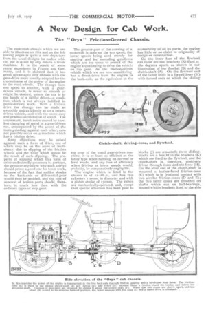
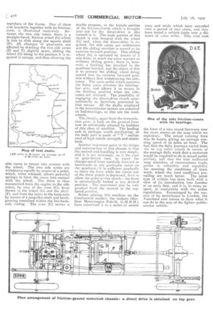
On the inner face of the flywheel rim there are two brackets (K) fixed at 18o degrees apart, as shown in our illustration of the flywhel (B) and the clutch-shaft (A). On the flywheel end of the latter shaft is a forged lever (H) with turned ends on which the sliding blocks (J) are mounted; these slidingblocks are a free fit in the brackets (K) which are fixed to the flywheel, and the clutch-shaft is, therefore, positively driven through them d.nd the lever (H). On the after end of the clutch-shaft is mounted a leather-faced friction-cone (C) which is in frictional contact with two similar friction-cones (D and E); the two latter cones are mounted on shafts which run on ball-bearings, housed within brackets fixed to the side members of the frame. One of these side brackets, together with its friction.. cone, is illustrated separately. Between the two side cones, there is a straight-faced, friction wheel (G) which is free to slide along the square shaft (F). All changes of gear-ratio are effected by drawing the two side cones (D and E) slightly apart, sliding the wheel (G) along to the position it is required to occupy, and then allowing the side cones to return into contact with the wheel. The two side cones are withdrawn equally by means of a pedal, which, when released, allows powerful springs to force the cones into contact with the wheel. The drive is thus transmitted from the engine to the side cones, by way of the cone (C), from thence to the wheel (G) and the shaft (F), and from the latter to the back-axle by means of a propeller-shaft and bevelgearing contained within the live-backaxle casing. The cone (C) serves a
double purpose, as the female portion of the friction-clutch which is brought into use for the direct-drive is also formed in it. The male portion of this clutch is cast integral with the wheel (G) and, when the direct-drive is required, the side cones are withdrawn and the sliding member is moved to its extreme forward position. This sliding wheel (G) is operated by means of a side lever, in much the same manner as ordinary sliding gears; there is, however, a limiting bar attached to the quadrant bracket, and the object of this is to prevent the sliding wheel being moved into its extreme forward position without first withdrawing the sidecones. The same pedal which operates the latter parts removes the limitingbar also, and allows it to return to the limitingposition when the sidecones are released. The possibility of engaging the direct-drive clutch unintentionally is, therefore, prevented by that means. All the shafts employed in the transmission system are mounted on ball-bearings, as also are the roadwheels.
The chassis, apart from the transmission gear, is built on the general lines now so universally adopted by builders of this class of machine. The leading axle is, perhaps, worth mentioning, as the body part is made of " T" section steel of high tensile strength and elastic limit.
Another important point in the asign and construction of this chassis is that the control and handling is very simple, and it is not necessary, as is the case on gear-driven cars, to move the change-speed lever carefully forward or backwards to any particular notch on the quadrant ; it is sufficient gradually to move the lever while the centre one of the three pedals is depressed, then to allow the pedal to rise slowly : the lever is automatically locked in any desired position. The movement may be very gradual from the neutral to the topspeed position.
Before placing this machine on the Continental market, the makers (Berliner Motorwagen Fabrik, have submitted it to a series of severe
tests and trials which have extended over a period of two years, and they have tested a vehicle lately over a distance of i-,600 miles. This trial took the form of a tour round Germany over the route shown on the map which we reproduce. The actual running time was So hours, giving an average running speed of 20 miles an hour. The fact that the daily journeys varied from x6x to 215 miles (much in excess of the average daily work that a motorcab would be required to do in actual public service), and that the tour embraced long stretches, of mountainous roads, points to reliability and capability for meeting the conditions of town work, where the road conditions prevailing are much better. The latest type of vehicle has been built with a view of its introduction into London at an early date, and it is, in every respect, in conformity with the police regulations. Encouraged by the success of its motorbuses in London, the Vaterland now means to show what it can do in the way of the lighter publicservice vehicle.