


A Design for a Compact Engine
Page 42
If you've noticed an error in this article please click here to report it so we can fix it.
A Resume of Patent Spectfications That Have Recently Been Published
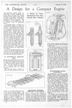
A LTH OUG H intended mainly for r %working aircraft auxiliaries, an engine shown in patent No. 572,749 possesses several features which would be useful in other fields. The engine is unusually compact, due to the novel arrangement of the cylinders. The patentees are Aero Engines, Ltd., and G. Halliday, both of Kingswood,
Bristol.• • The drawing shows a section of a four-cylindered engine in which the cylinders are arranged at the corners of a square. One of each pair of cylinders is inverted and drives one of the two crankshafts. The latter carry gears meshing with a central shaft, which forms the power output member: this functions also as a camshaft, the reduction ratio being 2 to L The valves are operated by push-rods and rockers, and the valve springs are unusual in that they are, in effect, torsion rods. Each pair of valves has a common torsion rod, and a tube (I) fitted over each end carries a fork (2), which embraces a waisted portion on the valve stem. The torsion rods are assembled under a prestressed load, which gives the valves their closing force. The arrangement has been covered by an earlier patent, No. 553,616.
As will be realized, the engine is very compact, the general shape being that of a square box. Any number of cylinders may be used, and their axis may lie horizontally instead of vertically, AN ELECTRICALLY OPERATED JACK ASE and convenience of use are the 11.1amain features of a novel jack shown in patent No. 572,684, by F. Lawton, 21, Chatsworth Street, Tibshelf, Derbyshire. The jack contains an electric motor to operate it, and it is intended to be powered from the vehicle batteries.
The drawing shows a section, in which the motor armature (I) is con nected, via a double reduction-gear (2) to the central screwed spindle. The motor has to be specially built around a tubular shaft, to permit the screwed spindle to descend through it. A reversing switch is included in the flexible lead, whilst a limit switch is provided to cut off the current at the position of maximum MEASURING CYLINDER PRESSURE IN OIL ENGINES I T is a matter of some difficulty to
measure accurately the compression pressure of an oil engine, because there is usually little access to the combustion chamber, and anything in the nature of an extension would affect the volume and thus give a false rading, • To overcoine these difficulties is the object of a
device shown in patent No. 572,712, by F. Hurrell, 16, Jubilee Cottages, Elthana, London, S.E.9.
This inventor proposes to dismantle one of the injectors and insert a pressure gauge therein. The drawing shows (left) the standard type of injector, and (right) the modifications required for the application of the pressure gauge. The needle valve, nozzle tip, closing spring and cap are removed, and their places are taken by the parts shown, comprising a ball-valved nozzle (1) and an upper assembly to carry the gauge. The fuel supply and leak-off passages are.blanked off by soft washers (2 and 3). When the engine is run on its other cylinders, the compression pressure can be directly read from the gauge, as the ball valve in the bottom holds a constant pressure and prevents the gauge from keeping time with the sweep of the piston.
BODYBUILDERS' CHASSIS SUGGESTION
ACHASSIS for a bus, coach or other heavy vehicle is shown in patent No. 572,240, which comes from specialists in bodybuilding, John C. Beadle, Ltd., and H. Hicks, both of 36, Spital Street, Dartford. The patent also discloses some of the problems besetting a bodybuilder who has to adapt his work to innumerable variations of different makers.
The proposed chassis, as clearly shown in the drawing, consists of four main girders united by built-up crossmembers. The latter are placed at frequent intervals, so that the whole area consists of a cellular framework. One of the cross-members is made extra high to form the support for the front bulkhead.
The engine and transmission units are to be placed in the most convenient positions, special emphasis being laid upon accessibility. Many of the smaller components can, it is suggested, be housed in the rectangular cells and other• openings in the frame.