


HINTS ON MAINTENANCE.
Page 68
If you've noticed an error in this article please click here to report it so we can fix it.
Improving the Petrol Supply on a Dennis. Advice on Reassembling a Subsidy A-type Maudslay Engine. A Hansa-Lloyd Fan-drive Improvement.
Preventing Jet Chokes on a Dennis.
USERS of Dennis vehicles who have experienced trouble caused through dirt in the petrol tank finding its way into the carburetter, may discover that the following tip will obviate this happening:—
Remove the cock from the tank and 'drill out the
threaded end to -15-c in. clearance. It is not necessary to drill it very deeply, but just sufficient to take the end of a piece of h-in. copper tubing, about 1 in. long, which should be tinned, pthsed into the end of the tap and securely soldered, afterwards the cock should be cleaned thoroughly and replaced in the tank. The tube projecting into the tank sump enables petrol to be taken from abov3 any dirt or water which may be present, and the sump may be cleaned out as occasion offers.
Reassembling a Maudslay Subsidy A-type Engine.--(Contd.)
IN a previous hint we promised to continue our advice on reassembling a Maudslay engine by dealing with the fitting of the cylinders.
These, together with their pistons and connecting rods, can be mounted in one operation. Having stneared the bores and pistons with engine oil, the pistons, which are already on the connecting rods, are pushed into their respective cylinders to the fullest extent. If new rings have been fitted, these, of course, must previously have been tried to see that they do not bind, and, when reassembling, their gaps must be properly spaced.
The cylinders, pistons and connecting rods can then be placed in position, with a brown-paper washer between cylinders and crankcase face to make a joint. It may be found advisable to smear this joint with shellac, boiled oil, or other jointing compound. The six bolts for holding down the cylinders are then inserted and tightened. The six foundation bolts are also employed for this purpose, the "third nuts" on these bolts, •to which reference was made in the previous hint, are run up to the underside of the upper half of the crankcase, leaving 1-64 in. between the face of each nut and the crankcase. On tightening the remaining six nuts the effect is to draw the halves of the crankcase tightly together, thus making the whole unit extremely rigid.
The big-end bearings can then be placed on their respective journals and the connecting rods pulled down to them, when the big-end hobs may be slid in and their nuts screwed up.
Mounting the cylinders, connecting rods and pistons in this way affords much less chance of broken or distorted piston rings, as is the case where the cylinder block is lowered on to pistons already mounted. There is also a considerable saving of time.
e46 The next procedure is to fit and screw down the valve seats, after which the cam box is mounted and the tappets adjusted, allowing .012 in. clearance on the inlet and .015 in. on the exhaust. This can be done without turning the engine, as the vertical shaft has not yet been mounted.
Following this, fix the timing pointer, on the rear cylinders and turn the engine until the timing mark "Inlet open 1 and 4" is in a line with the pointer. The camshaft is then turned in the direction of rotation until inlet valves Nos. 1 and 4 are just about to open. The vertical shaft may then be placed in position with the universal ball at the top, taking care to place the forks at right angles to each other ; otherwise, the cam box cannot be hinged back. The two primary timing gears should mesh without any trouble. An error of not more than in. either way of the timing marks on the flywheelis permissible, although not advisable. The skew gear end cover is then fitted, thereby retaining the vertical shaft.
When fitting the starting handle on the crankshaft splines, the starting dog should be vertical with the crankcase at top dead centre; if this be not so fitted, much difficulty will be experienced when starting the engine, owing to the compression being felt on the starting handle in the position where the operator has the least power by which to overcome it.
After fitting the engine into the chassis, the oil pump, the oil filter in the base and the oil pipe can be mounted. The suction pipe from the oil pump to the filter should be filled with oil, thereby ensuring an Immediate supply when the engine is started. Finally, the crankcase doors should be returned to their proper position.
Improving the Fan Drive on a Hansa-Lloyd.
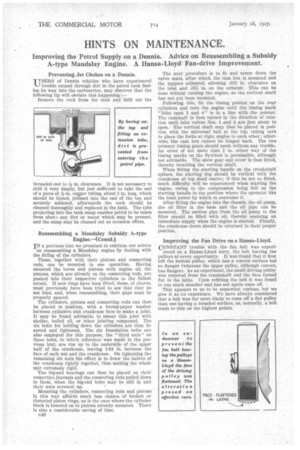
CONSTANT trouble with the fan belt was experi enced on a Hansa-Lloyd lorry, the belt leaving the pulleys at every opportunity. It was found that it first left the bottom pulley, which has a convex surface but no flanges (whereas the upper pulley, although convex; has flanges). As an experiment, the small driving pulley was removed from the crankshaft and the face turned flat in the lathe. Upon refitting the belt it was found to run much steadier and has not again come off. .
This appears to us to be somewhat curious, but we give it as an experience. We have always considered that a belt was far more likely to come off a flat pulley than one having a rounded surface, as, normally, a belt tends to ride on the highest points.