


A ONE-MAN HOOD FOR MOTOR COACHES.
Page 32
If you've noticed an error in this article please click here to report it so we can fix it.
A Résumé of Recently Published Patents.
A determined attempt to solve the problem of the provision of a one-man hood for chars-A-banes is made by Clayton and Co., and described in specification No. 154695. The principal object which is achieved 'by the patentees of this invention is to • arrange means whereby the hood, when not in use, may be folded away entirely out of sight and in such a manner that there are no projecting brackets or other parts expanding upwards above -the vehicle body, either at the sides or at the ends of the vehicle. The entire hood and its supports are hidden from view when it is lowered, with ease, by one man.
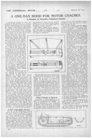
The first point to notice about, the design' of this hood is that it is erectedand taken down laterally and not longitudinally, as usually is the case. • The compartment for its accommodation is disposed along the off side of the char-A-banes and runs the full length of the vehicle: Except in particularly long hoods, there will need only to be two sets of vertical supports—one immediately behind the driver's seat, the other at the extreme rear of the maebine. A description of one set of these supports should be of interest, and reference should be had to the accompanying illustrations when reading the following note.
Behind the driver's seat (we are confining, our attention for the moment to one set of supports) are pivoted three vertical swinging levers. Their ends, and the pivots on which they are carried, are covered by 4 deep, vertical box, into which, when the hood is lowered, the three pillars subside. Outside this box are a couple of guide bars; upon which slides abracket. Pins on this bracket project inside the flat box, and one of them is the pivot of the off-side supporting pillar. The other pivot is coupled isy means of a link to the near-side sup-. porting pillar. The centre pillar swings freely on a pisiot attached to .thesbacis of the seat. Inside the horizontal elide bars are long springs, whichrbear at one end on the end of the bars and, at the other, upOn inwardly projecting pins fastened to the sliding bracket, The arrangement of the links and springs is such that, as the hood is pulled down from the off side of the chassis, the other pillars automatically awing over and fold upon one another within the box provided for their reception. The springs within the tubular slide bars assist in this opuratien.
A -New Caterpillar Tractor.
Thu use of the track'-laying type of tractor is growing in theStates, as all who have access to American journals, or who are acquainted With conditions over there, will be aware. The Holt Manufacturing Co. have patented a design of caterpillar tractor, and the specification appeared last week in the name of Caterpillar Tractors, Ltd., being No. 154398. -The object of the invention is that of producing a small tractor of light weight and neat appearance,: hiscombina
tion with facility of construction. There are, of course, no dimensions whatever in E28 the specification itself, but the machine appears to be one which 'would compete as regards itssize and weight with the well-known eletrae tractor.
The subject matter of the patent is mainly in regard to slotaile, of construction, and these are described with that fullness which is a peculiarity of American patent. specifications.
The principal innovation appears to be in regard to the construction of the frame itself, which is of pressed steel, cradle shaped, so. as partly to surround the engine. At 'the front and rear of the frame ase suitably-designed castings, the rear one of which is supported by a transverse spring, the ends of which slide in' spherical supports in brackets attached to the truck frames,, which are supported on the tracks. The front ...end of the tractor is carried on a central, horizontal pivot, which is itself supported by a transverse spring similarly arranged to that of the rear. The complete suspension of the tractor frame is, as will have been noted, three-point.
Other Patents of Interest.
A novelty in torque members is described by the Associated Equipment Co., Ltd., in specification No. 154697. Instead of adopting the usual construction in regard to yhis component, of pivoting it at its rear end tothe back axle casing, it is firmly bolted to brackets on that easing, lint is made of flexible material so
arranged that it will accomodate itself to movements of the rear axle in a vertical , plane through its axis. A new and ingenious type of magneto is described in specification No. 1W89 by R. A. Williams. Permanent mag nets are disposed in the engine flywheel in such a manner that their poles are in a line with the circumference 'of the flywheel. One or more stationary • armatures are disposed round the flywheel, and a make and break device is incorporated in the design. The inventor claims that this device is simpler in construction and operation, and cheaper to produce as an article • of manufacture, than the ordinary magneto.
The change speed gear, which is the subject of patent No 154694 by 2. -IL C. Faire is of
the type in which friction clutches are used to facilitate changes of gear. Attention need only be directed to the arranges merit of the clutches, the rest of the mechanism is on more or less familiar lines. The main clutch is of the disc type. The front cover, which is bolted to the flywheel and encloses this clutch, is provided with a boss which is splines11.o accommodate the exaggerated, castellated, operating sleeve of the clutch, which is Controlled by a pedal in the usual manner. It 'is, how• ever, continued rearwards and with it is formed integrally the male component of a cone type friction clutch, The latter is, therefore, direct driven by'the engine through 'the operating sleeve. It will now be appreciated that forward movement of the clutch pedal engages the cone clutch, its release allowing engagement of the main clutch in the usual manner. The gears box is suitably arranged to take advan tage of the facilities afforded by two clutches, and the patentee draws attention particularly to the fact that, in cireum'stances such as those encountered by a driver who, on, rounding a corner, sud denly encounters a steep hill, it is possible . to effect a suitable change of gear by operation of the clutch pedal only.
Thetyre described in No. 154753 by J. B. Moore incorporate§ the features of the solid and pneumatic.
An ingenious magneto coupling is described in No. 154857 by F. B. Ram. The principle' of the nut and cone union is adopted for this coupling.
In No. 154438 .a method of constructing front axles is described by the Chassis Coastruction Cis., Ltd.